Welder not welding: no arc, a weak arc or an arc that keeps breaking — step-by-step checks
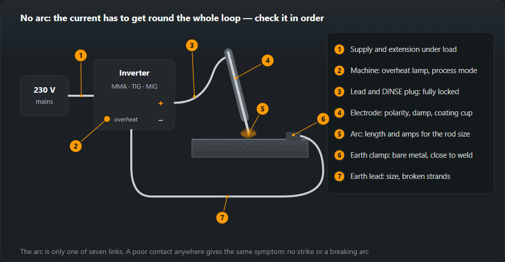
The inverter lights up, the fan runs, and there is no arc — or there is one, but it is weak and keeps going out. Nine times out of ten the machine is fine: one of the seven links the current has to pass through is letting it down. Below is the order of checks from cheapest to most expensive, with figures from our calculators.
Short answer
Check in order: supply (extension fully unwound and heavy enough), earth clamp (bare metal, close to the weld), leads and DINSE plugs (locked home, not running hot), mode and polarity (MMA/TIG/MIG, basic rods on DC+), amps for the rod size (2.5 mm — 70–100 A), the electrode (dry, no coating cup on the tip) and the overheat lamp (duty cycle). On MIG add wire feed, contact tip and gas; on TIG, the tungsten and the arc-start method. Only when all of that is right and there is no voltage at the terminals are the electronics to blame.

By symptom: where to start
We use the same set of symptoms in our article on servicing a welder; the table says where to look first.
| Symptom | Look at |
|---|---|
| Will not strike | Earth clamp, polarity, a break in the holder, a damp electrode |
| Cuts out after a few minutes | Duty cycle exceeded, blocked vents, dust-clogged interior, ambient temperature |
| Weak arc at rated current | Earth clamp, cable size, connectors, supply voltage under load |
| Unstable arc, wandering current | Contact tip (MIG), loose connector, dirty tungsten (TIG) |
| Trips the supply | Breaker curve, circuit rating, coiled extension drum |
| Trips the RCD | Damp, damaged lead, moisture inside the machine — a genuine fault, not a nuisance |
| A connector runs hot | Tightness, an oxidised contact face |
| Erratic wire feed | Liner, feed rolls, contact tip |
The first four rows are what this page is about. Tripping the supply is covered separately in welder trips the breaker, and erratic feed in wire feeding problems.
Order of checks
- Supply: socket, extension lead, voltage under load.
- Earth clamp: clean metal, firm grip.
- Welding leads and connectors: tightness, size, broken strands.
- Process mode and polarity.
- Amps for the rod size and arc length.
- Electrode: damp, coating cup on the tip.
- Thermal protection and duty cycle.
- MIG/MAG: wire feed, contact tip, gas.
- TIG: tungsten, gas, arc start.
The order is deliberate: the first five points take a few minutes without tools, and between them they account for most “my welder doesn’t work” complaints.
1. Supply and extension lead
An inverter needs voltage not at an unloaded socket but at the moment the arc draws current. On a 4.0 mm rod (160 A) an inverter draws about 23 A from the mains — that is what our duty cycle calculator gives at 230 V. At that current a 25 m extension with 1.5 mm² cable loses about 13 V, and 2.5 mm² about 8 V. The welder then gets noticeably less than 230 V and either gives a weak arc or trips its under-voltage protection.
- Unwind the drum completely. A coiled extension cannot shed heat: at welding currents it runs hot, its resistance rises and the insulation can soften.
- Keep it short. Losses rise in proportion to length. If you have to choose between a longer extension and longer welding leads, work both out in the voltage drop calculator.
- Check the socket and plug. A scorched plug is a resistance where the voltage disappears.
- Generator. An undersized generator gives the same symptom as a thin extension: the arc sags on striking. Size the generator from the welder’s rating plate.
2. Earth clamp
The most common cause of no arc and the most overlooked. A clamp on paint, rust, zinc coating or on the bench instead of the workpiece conducts badly or not at all. Symptoms: the arc will not strike, strikes only when scratched, keeps breaking, and the clamp itself gets warm.
- Put the clamp on bare metal — grind a spot if necessary.
- Put it close to the weld, ideally on the workpiece itself. Current through hinges, bearings or bench bolts finds its way through contacts never meant for it.
- Check the spring and jaws. A slack clamp with burnt jaws gets replaced — it costs less than an hour of fault-finding.
- Check the lead-to-clamp joint: crimped lug, tight bolt, no green copper oxide.
3. Welding leads and connectors
The electrode lead and the earth lead are one loop, so their losses add up. Our welding cable size calculator uses ΔU = 2·ρ·L·I/S. Examples at 160 A, copper ρ 0.0175:
- 10 m of 16 mm² — about 3.5 V, roughly 14 % of a typical 25 V arc. Still acceptable.
- 10 m of 25 mm² — about 2.2 V.
- 20 m of 16 mm² — about 7.0 V. The arc is clearly weaker than the dial says; the voltage drop page flags this as too much (over 4 V).
DINSE plugs must be pushed in and twisted until they stop. A loose plug arcs, heats up and in time melts the socket in the machine. A lead with broken strands (typically at the holder and the clamp, where it flexes) looks fine from outside — you find it by touch after a few minutes of welding: it gets hot in one spot.
4. Process mode and polarity
Multi-process inverters have an MMA / TIG / MIG switch. In TIG lift mode the machine only gives current after the tungsten touches and lifts, so a stick electrode “doesn’t work”; in MIG mode current appears when you press the torch trigger. Also check that remote or pedal control is not switched on with nothing plugged in.
Polarity depends on the coating — the same data as our electrode coating table:
- Basic (B) — DC+, electrode positive. On negative the arc is restless and breaks.
- Rutile (R, RR, RC) — AC or DC either polarity.
- Cellulosic (C) — DC+ or AC.
- MIG/MAG with solid wire — torch positive. Self-shielded flux-cored wire (114) often needs the opposite connection — check the spool label.
- DC TIG — torch negative.
5. Amps for the rod size and arc length
Too little current gives an arc that sticks the rod or dies right after striking. Ranges from our current table: 2.0 mm rod — 50–80 A, 2.5 mm — 70–100 A, 3.2 mm — 90–140 A, 4.0 mm — 130–190 A. Start mid-range and adjust.
Arc length is the other half: an arc longer than the rod diameter loses voltage across the air gap, spatters and goes out. Hold the rod so the arc is about equal to its diameter; sticking is covered separately in electrode sticking.
6. Damp or damaged electrodes
A coating that has picked up moisture strikes poorly, gives a restless arc and a porous weld. The other cause is the “cup”: burnt coating standing proud of the core wire after the last arc break. It insulates the core and stops the arc striking; tap the rod end on the metal to knock it off. Drying by coating type:
| Coating | Temperature | Time | Storage afterwards |
|---|---|---|---|
| Rutile | 70–120 °C | 1–2 h | A dry place; the sealed packet is usually enough |
| Basic | 300–350 °C | 2 h | Quiver at 100–150 °C; an opened packet goes back to the oven |
| Cellulosic | no more than 70–80 °C | — | Sealed packet — drying is not allowed |
| Acid | 100–150 °C | 1 h | A dry place |
Basic rods go into a heated quiver after the oven; rutile ones are usually fine in a dry place. Cellulosic rods are never dried.
7. Thermal protection and duty cycle
An overheat lamp and the arc suddenly dying after a few minutes means the thermal cut-out has tripped — not a fault. Duty cycle to EN 60974-1 is counted over a 10-minute period. The duty cycle calculator converts the rating-plate figure to another current with X₂ = X₁·(I₁/I₂)². Example for a welder rated 60 % at 160 A:
- at 200 A — about 38 %, i.e. about 3.8 minutes of arc in 10;
- at 120 A — 100 %, continuous.
If the cut-out trips much sooner than the duty cycle suggests, cooling is to blame: blocked vents, dust on the heatsinks, a machine pushed against a wall or standing in full sun. After it trips, do not unplug the welder — the fan must keep running to cool it.
8. MIG/MAG: wire feed, contact tip and gas
- Contact tip. Oversized or worn — current transfers to the wire unreliably and the arc jumps. Undersized or clogged with spatter — the wire stops.
- Drive rolls and tension. A roll for another wire size or too little tension lets the wire slip and gives an arc that burns and dies by turns.
- Liner. A dirty or kinked liner drags on the wire and it feeds in jerks. Details in wire feeding problems.
- Gas. No gas does not kill the arc, but it crackles and spatters and the weld is porous. Typical MAG flow is 10–16 l/min; check the cylinder, regulator and solenoid (you hear it click when you press the trigger).
- Voltage for the wire speed. Too much wire for the voltage and it stubs into the work and pushes the torch back; too little and the arc is long and unstable.
9. TIG: tungsten, gas and arc start
- Contaminated tungsten. After dipping into the pool the tip is coated in metal and the arc wanders. Regrind the tungsten; wiping it is not enough.
- Arc-start method. With lift start the tungsten touches the work and is lifted; with HF a spark jumps without contact. HF that only crackles with no arc usually means too big a gap, no gas or a poor earth.
- Gas. Argon, typically 6–10 l/min for steel. Without gas the tungsten oxidises quickly and the arc becomes unstable.
- Polarity and mode. TIG torch negative; for aluminium, AC if the machine has it.
When it really is the welder
If the circuit is sound and there is still no arc, measure the voltage between the terminals with the welder on and no load. It should be close to the open-circuit voltage U₀ on the rating plate (noticeably lower with VRD switched on — that is normal). No voltage, an error code on the display, a fan that does not run or a burning smell means a job for a service centre.
The capacitors in an inverter hold a dangerous voltage long after it is unplugged. The checks on this page stop at the external circuit; the inside of the machine is a job for a service technician.
Common mistakes when fault-finding
- Turning the amps up instead of finding the bad contact. More current through a poor earth clamp just heats the clamp more.
- Earthing on the bench. The current then goes through the bench-to-workpiece contact — a point never meant for it.
- A new box of rods straight onto the job. Basic rods from an opened box can behave like a “broken welder”.
- Switching the welder off after the thermal cut-out trips. The fan stops cooling and the wait gets longer.
- An extension left on the drum. It heats up, loses voltage and can trip the protection.
Frequently asked questions
My inverter welder turns on but won’t weld — where do I start?
With the current path, not the electronics. The arc is only one link: the current has to pass through the socket and extension lead, the machine, the lead and holder, the electrode, the workpiece, the earth clamp and the earth lead back. The usual culprits are an earth clamp on paint or rust, a DINSE plug not locked home, the wrong polarity or damp electrodes. Only when all of that checks out and there is no open-circuit voltage at the terminals do you look for a fault inside the machine.
Why does my arc keep breaking?
Most often an arc held too long, too little current for the rod size (70–100 A for 2.5 mm, 90–140 A for 3.2 mm) or a loose contact somewhere in the circuit — earth clamp, connector, broken strands in a lead. With basic (low-hydrogen) rods, AC or reversed polarity is another common cause: they run on DC+.
The arc is weak even with the amps turned up — what should I check?
Voltage lost on the way. A long, thin mains extension can take more than ten volts: at about 23 A over 25 m, 1.5 mm² cable loses about 13 V and 2.5 mm² about 8 V. On the welding side, 10 m of 16 mm² lead at 160 A loses about 3.5 V. Add hot connectors and an earth clamp on dirty metal.
The welder cuts out after a few minutes and a lamp comes on — what does that mean?
The thermal protection has tripped: the duty cycle was exceeded or the machine is not cooling properly. Duty cycle is counted over 10 minutes. A welder rated 60 % at 160 A has only about 38 % at 200 A — under 4 minutes of arc in 10. Do not switch it off at the wall: the fan has to cool it, and the lamp goes out by itself.
Can damp electrodes refuse to strike?
Yes. A damp coating strikes poorly, the arc is unstable and the weld porous. Basic electrodes are baked at 300–350 °C for 2 hours, rutile ones dried at 70–120 °C for 1–2 hours. Cellulosic electrodes must not be dried — keep them in the sealed packet.
My MIG welder feeds wire but there is no arc — why?
Wire is coming out but no current is flowing: usually an earth clamp with no contact, the wrong polarity (solid wire runs with the torch on positive), a worn or oversized contact tip, or a break in the torch lead. No gas does not stop the arc, but it gives a crackling arc and a porous weld — a separate fault.
Updated: