Why MIG wire jams, slips or birdnests and how to fix it
Feeding faults account for most of the downtime on a semi-automatic set, and almost all of them are consumables rather than the machine. Work along the path the wire takes and you will find it.
The contact tip
Start here, always. The tip carries the current into the wire through a hole that the wire is constantly rubbing. It wears oval, then the wire arcs inside it instead of sliding, and the symptoms are a stuttering arc, wandering current and eventually burnback — the wire fusing to the tip.
A tip is the cheapest part in the system and the most frequent cause of trouble. If the hole has gone from round to oval, or you can see a groove worn on one side, replace it. On heavy work a tip may last a shift; nobody has ever regretted changing one too early.
The liner

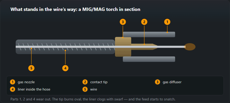
The steel spiral or PTFE tube the wire runs through inside the torch cable. Fills with swarf and dust from the wire, kinks if the torch is coiled tightly, and eventually the friction exceeds what the drive rolls can push against.
Blow it through with compressed air from the machine end. Replace it if the torch has been dropped, run over or coiled around something tight. And lay the torch out straight while welding rather than in a loop on the floor — a coiled torch cable is a liner working at a permanent disadvantage.
Two liner rules that catch people: a steel liner is for steel wire and a PTFE one is for aluminium and stainless, and the liner must be cut to the right length so it seats against the back of the contact tip. A liner cut short leaves a gap where the wire buckles.
The drive rolls
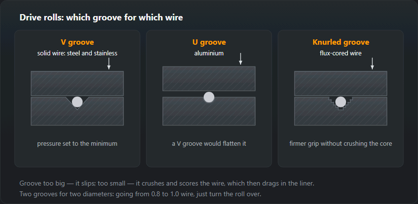
Three things to get right. The groove profile: a V groove for solid steel wire, a knurled groove for flux-cored, a U groove for aluminium. Using a V roll on soft aluminium wire flattens it. The size: rolls are stamped with the wire diameter, and a 1.0 mm roll on 0.8 mm wire slips. The pressure: enough that the wire does not slip and no more.
The spool and the brake
Too much brake and the rolls fight the spool; too little and the spool overruns when you release the trigger, throwing a loose loop that jams on the next start. Set it so the spool stops within about a quarter turn of releasing the trigger.
Also check that the wire has not slipped off the side of the spool and jammed under a turn. That produces a sudden hard stop that looks exactly like a liner blockage.
| What happens | Where to look | What to do |
|---|---|---|
| The arc dances, its length keeps changing | A worn contact tip | Replace it: the bore wears oval and no longer holds the wire centred |
| The wire feeds in jerks | The torch liner | Blow it out or replace it; check it suits the wire diameter |
| The roller turns, the wire stands still | Roller pressure or the wrong groove | Tighten the pressure, fit the roller for that diameter and wire type |
| The wire crumples ahead of the rollers | Too much pressure, or a jam further along | Ease the pressure and clear the jam, or it comes straight back |
| The wire has welded itself to the tip | Too little stick-out, too much voltage | Stick-out 10–15 mm; check the settings against the thickness |
| The wire slips off the spool in a loop | The spool brake has gone slack | Tighten the brake: the spool must not coast on |
| Swarf and copper dust in the feeder | The roller is grinding the wire away | Look for the jam further down the line; do not crank the pressure |
Diagnostic order
- Change the contact tip. Half the cases end here.
- Feed with the torch straight and unloaded: if it feeds smoothly now, the cable routing was the problem.
- Remove the tip and feed the wire out by hand-triggering — smooth means the liner is fine, notchy means it is not.
- Check the roll profile, size and pressure.
- Check the spool brake and that the wire is not trapped on the spool.
The consumables and their symptoms are described in more detail in MIG/MAG torch consumables.
The five-minute test: where the problem is
- Unplug the torch from the Euro connector and inch the wire out dry, with no arc. If it runs smoothly, the cause is in the cable or torch. If it jerks as it leaves the feeder, look at the spool, the brake and the rolls.
- Check the pressure by hand. Pinch the wire in a gloved hand past the rolls: the rolls should slip while the wire stays put. If you cannot stop it, the pressure is too high.
- Pull the wire through the cable. With the tip off, wire in a straight cable slides by hand with light, even resistance. A local snag means a kinked or clogged liner.
- Hold the tip up to the light. An oval, melted bore or a stuck spatter ball — replace it.
The order is deliberate: cheapest and quickest first. Most cases end at the tip or the liner.
Check the actual wire feed speed
Set the feeder to, say, 6 m/min, shut off the gas, pull the trigger for 10 seconds and measure the wire that came out. It should be 1.0 m (6 m/min × 10/60 min). Clearly less with smooth feeding means slipping rolls or drag in the line; less with jerking means a snag in the liner. The test also shows whether the dial is marked in real metres per minute at all, which is not a given on cheaper machines. The feed a given current should need is worked out by the wire feed speed calculator.
The liner: choosing and replacing it
- Type. Steel spiral for steel wire, PTFE (Teflon) for aluminium and stainless. The bore to suit the wire diameter range printed on the liner packet.
- Length. Cut a new liner with the cable laid out straight and deburr the end. Too short leaves a gap at the connector where the wire kinks; too long and it is compressed and drags.
- Cleaning. At every spool change blow the liner through with compressed air from the torch end. Copper dust and shavings from the rolls are the main cause of jerky feeding on an old cable.
- When to replace. When blowing out does not help, when the cable has been kinked sharply, or when you switch from steel wire to aluminium — a liner used for steel is not used for aluminium.
Birdnesting — where it comes from
A tangle of wire between the rolls and the connector is always the same mechanism: the wire jammed further down and the rolls kept pushing. The jam is most often wire burnt back onto the tip, a clogged liner or a tip that is too small. Too much roll pressure makes the rolls push at full force instead of slipping — and the nest grows in a second. Once untangled, cutting the wire is not enough: find and clear the jam first, then back off the pressure.
Drive rolls: V, U and knurled grooves
A V groove is for solid steel and stainless wire, U for aluminium, which a V would flatten, and knurled for flux-cored wire, which needs a firmer grip without being crushed. Rolls usually carry two grooves for two diameters, marked on the side; going from 0.8 to 1.0 wire just means turning the roll over. A groove too big for the wire slips; too small and it crushes and scores the wire so that it starts dragging in the liner.

The contact tip: size and wear
The tip bore is marked with the wire diameter. For aluminium wire the usual choice is one size up (a 1.2 tip for 1.0 wire, for example), because aluminium expands as it heats and seizes easily. Replace the tip when the bore starts going oval — do not wait for the wire to burn back onto it. Long runs at high current heat the tip more and wear it faster; a few spares at the bench cost less than an hour of downtime.
If feeding is smooth and the weld is still porous, the gas is to blame, not the wire — see porosity in welds. MIG settings by thickness are on the MIG/MAG welding page, and what is left on the spool is worked out by the wire length on a spool calculator.
Frequently asked questions
What is birdnesting?
The wire jams somewhere ahead of the drive rolls, the rolls keep turning, and the wire piles up between them and the inlet guide into a tangle. It is a symptom, not a fault: something downstream stopped the wire, almost always a worn contact tip or a kinked liner.
How tight should the drive roll pressure be?
Just enough that the wire does not slip. Set it by feeding into your gloved hand: the wire should stop or slip when you press against it, not deform. Over-tightening flattens the wire, which then will not pass the liner — the cure becomes the cause.
The arc stutters but the wire feeds fine.
Then it is electrical contact, not feeding. The contact tip is worn oval and the wire is arcing inside it instead of making solid contact. A tip is a consumable that costs almost nothing; change it before investigating anything else.
How do I replace the liner in a MIG torch?
Take out the wire, unscrew the tip and nozzle, remove the liner nut at the Euro connector and pull out the old liner. Feed the new one in from the connector end with the cable laid straight, cut it to length with a little allowance for the nut, deburr the end and tighten.
How do I check the wire feed speed?
Set, say, 6 m/min, pull the trigger for 10 seconds with no arc and measure the wire: it should be 1.0 m. Clearly less means slipping rolls or drag in the liner.
Which contact tip for aluminium wire?
Usually one size larger than the wire, e.g. a 1.2 tip for 1.0 mm wire: aluminium expands as it heats and seizes in a close-fitting bore.
Updated: