Which MIG/MAG torch parts wear out and what each symptom means
A MIG torch is four consumables and a handle. Each wears at a different rate and each produces its own symptom — which makes the torch the easiest part of the machine to diagnose, once you know which part gives which.
The four parts

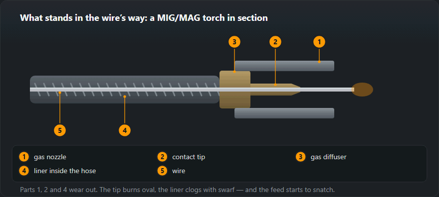
| Part | Job | Symptom when worn | Life |
|---|---|---|---|
| Contact tip | Carries current into the wire | Stuttering arc, wandering current, burnback | Hours to a shift |
| Gas nozzle | Shapes the gas shield | Porosity, visible spatter build-up | Cleaned hourly, replaced after weeks |
| Gas diffuser | Spreads the gas evenly | Turbulent shield, porosity despite good flow | Weeks |
| Liner | Guides the wire down the cable | Erratic feed, birdnesting | Months |
| Feed rolls | Push the wire | Slipping, swarf shaved off the wire | Months |
The contact tip
Current passes into the wire through a hole the wire is constantly rubbing. The hole wears oval, contact becomes intermittent, and the arc starts to stutter. Left long enough, the wire fuses to the tip — burnback — and the tip is finished anyway.
Buy the right size: a 1.0 mm tip for 1.0 mm wire. Aluminium is the exception, because it expands more when hot, so aluminium wire runs in a tip one size larger. And check the tip is tight — a loose tip arcs against the diffuser and destroys both.
The nozzle
Spatter builds up inside it and gradually strangles the gas flow. The result is porosity that survives every adjustment of the flowmeter, because the problem is downstream of it. Clean it with pliers and a reamer, or replace it — a nozzle with the spatter chipped out badly enough to score the bore no longer shapes the shield.
Nozzle diameter follows the current: about 12 mm up to 200 A, 15–16 mm above that. Too small a nozzle at high current gives a shield that does not cover the pool; too large a one wastes gas.
The liner
The most overlooked part, because it is invisible. It fills with dust and swarf from the wire, and as friction rises the drive rolls have to push harder until eventually the wire buckles and birdnests.
Blow it through with compressed air from the machine end when you change the spool. Replace it if the torch has been dropped or run over. Cut it to length so it seats against the back of the contact tip: a liner cut short leaves a gap where the wire has room to buckle, and that fault is maddening to find.
The cable itself
Lay the torch out straight while welding. A cable coiled on the floor makes the wire negotiate several extra bends, which is friction you have added for nothing — and it is the single most common reason a torch that fed perfectly on the bench misbehaves on the job. The rest of the feeding fault tree is in wire feeding problems.
Sizing a torch to the current: what “250 A at 60 %” means
A torch, like a power source, is rated at a current for a given duty cycle over a ten-minute period. “250 A at 60 %” means the torch can run at 250 A for 6 minutes in every 10 and must then cool. Unlike the welder, a torch has no thermal cut-out — overloaded, it simply gets hot, and the first to suffer are the contact tip, the gas diffuser and the handle insulation.
Converting to another current uses the same square law as the duty cycle calculator: duty cycle scales with the square of the current ratio.
- At 200 A: 60 % × (250 / 200)² ≈ 94 % — nearly continuous.
- Continuous (100 %): 250 × √0.6 ≈ 194 A.
- At 280 A: 60 % × (250 / 280)² ≈ 48 % — under half the time.
This is an estimate for comparing torches; the manufacturer’s data is what counts. The working rule: pick a torch whose rating sits clearly above your typical welding current, because long flat-position seams come close to continuous duty.
CO₂ or mixed gas: why the rating drops
Manufacturers often give two ratings on a torch: one for CO₂ and one for M21 argon mix. The second is lower. An arc in argon-rich gas radiates more heat onto the nozzle and tip, so the same torch runs hotter at the same current. If you weld in M21 and the catalogue only shows the CO₂ figure, allow a margin. Which gas suits which job is covered in shielding gas selection.
Contact tips: bore, thread, material
| Feature | What to check | The mistake that happens |
|---|---|---|
| Bore | Stamped on the tip, equal to the wire (0.8 / 1.0 / 1.2); larger for aluminium | A 1.0 tip on 0.8 wire — the arc wanders from the first minute |
| Thread | M6 on smaller torches, M8 on larger ones — to match the diffuser | A tip that “nearly fits” and sits on two threads |
| Material | E-Cu copper for general work, CuCrZr for high current and long shifts | The cheapest unmarked tips wear oval faster |
| Tightening | Snug with a spanner or pliers, without force | A finger-tight tip overheats at the joint |
Tip thread and length must match the diffuser of that particular torch series — buy replacements by the torch designation, not by eye.
Nozzles and tip position
- Cylindrical — the widest gas cover, for butt welds and long flat runs.
- Conical — for fillets and tight corners; the narrower bore clogs faster, so it needs cleaning more often.
- Tip position. For short-circuit transfer on thin sheet the tip sits flush with the nozzle or stands slightly proud; for spray transfer and high current it is recessed inside the nozzle, away from the pool and the heat.
Wire stick-out from the nozzle is kept at about 10–15 wire diameters; moving the tip does not change that rule. The link between feed speed, current and stick-out is worked through in the wire feed speed calculator.
Worked example: a shop torch for 1.0 wire in M21
A steel fabrication shop, 1.0 mm wire, 180–220 A welding current, M21 gas, fillet welds a few tens of centimetres long.
- The highest working current is 220 A. A torch rated “250 A at 60 % with CO₂” gives about 60 % × (250 / 220)² ≈ 77 % at 220 A, but its rating in M21 is lower — the margin shrinks.
- Conclusion: either one torch size up, or check the catalogue for the mixed-gas rating.
- 1.0 tips with the thread to suit the diffuser; CuCrZr on two shifts.
- A conical nozzle for fillets and silicone-free anti-spatter spray.
- A steel liner blown out monthly — see welder servicing.
Common torch mistakes
- Knocking the nozzle on the job to shake spatter off. The insulator cracks and the nozzle goes live — the arc jumps to the nozzle.
- A missing or damaged diffuser. Gas comes out unevenly and spatter gets inside the torch.
- Grinding spatter off the tip. The bore loses its roundness; replacing the tip is cheaper and quicker.
- Overloading the torch “because the welder gives more”. The machine rating is not the torch rating — the weakest link decides.
Frequently asked questions
How often should the contact tip be changed?
When the hole is no longer round, which on heavy work can be within a shift. It is the cheapest part in the system and the most common cause of a stuttering arc, so the honest answer is: sooner than you think, and certainly before you start investigating the machine.
Does anti-spatter spray matter?
It saves the nozzle, which is the second most expensive consumable. Spray or dip the nozzle and the tip, but keep the spray away from the joint itself — silicone residue in the weld causes porosity, and that fault is hard to trace back to a can on the bench.
Steel liner or PTFE?
Steel for steel wire, PTFE for aluminium and stainless. A steel liner scrapes soft aluminium wire and fills with the shavings; PTFE is too soft to survive steel wire for long. Using the wrong one produces feeding faults that look like everything else.
What size MIG torch for a 200 A welder?
One whose rating sits clearly above your typical current. A torch rated 250 A at 60 % runs about 94 % of the time at 200 A by the square law, so it suits a 200 A machine. If you weld in M21 mix, check the mixed-gas rating — it is often lower than the CO₂ one.
M6 or M8 contact tips?
The diffuser of your torch decides: smaller series usually take M6, larger ones M8. Buy tips by the torch designation and wire size rather than the thread alone, because the lengths differ too.
Are CuCrZr contact tips worth it?
Copper-chromium-zirconium is harder and holds up better at temperature, so the bore wears oval more slowly. It pays off at high current and on two-shift work; for occasional welding a standard E-Cu copper tip is perfectly adequate.
Updated: