Wire feed speed and deposition rate
On a MIG/MAG machine the wire feed speed is the current: set one and the other follows. This converts between them, and tells you how much metal per hour that means.

Why they are linked
A constant-voltage power source holds the arc length by adjusting its output until the wire burns off exactly as fast as it is fed. Push more wire in and the machine answers with more current. That is why a MIG set has a wire speed knob and not an ampere knob, and why two machines set to the same amps can behave quite differently if the stick-out is not the same.
Stick-out changes everything
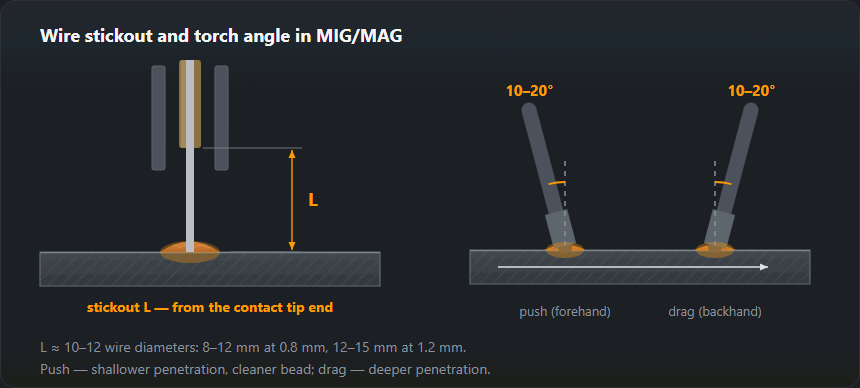
The free length of wire between the contact tip and the arc is a resistor. Longer stick-out preheats the wire more, so it melts at a lower current and the penetration drops even though nothing on the panel has changed. Keep it at about 10–15 mm for short arc and 15–25 mm for spray, and keep it constant — a stick-out that wanders is a common cause of a bead that varies along its own length.
Deposition rate is what turns this into money: multiply it by the price per kilogram and the hours, and you have the input for the cost per metre.
Diameter, current and feed
| Ø, mm | Working current, A | Feed, m/min | Metal thickness, mm |
|---|---|---|---|
| 0.8 | 60–180 | 3–12 | 0.8–4 |
| 1.0 | 100–250 | 4–11.5 | 1.5–8 |
| 1.2 | 140–330 | 3.5–10.5 | 3–15 |
| 1.6 | 240–450 | 4–8 | from 8 |
The feed column is worked out with the same formula the calculator above uses, so the table and the result cannot drift apart.
Current and wire feed speed table
The table above gives ranges; this one breaks them down every few tens of amps, with the mass of wire a MIG set melts in an hour of arc. The figures come from the same coefficients as the calculator.
| Ø, mm | Current, A | Wire feed, m/min | Wire melted, kg/h | Into the weld (Ar+CO₂), kg/h |
|---|---|---|---|---|
| 0.8 | 60 | 3.0 | 0.71 | 0.67 |
| 0.8 | 100 | 6.0 | 1.42 | 1.35 |
| 0.8 | 140 | 9.0 | 2.13 | 2.02 |
| 0.8 | 180 | 12.0 | 2.84 | 2.70 |
| 1.0 | 100 | 4.0 | 1.48 | 1.41 |
| 1.0 | 150 | 6.5 | 2.40 | 2.28 |
| 1.0 | 200 | 9.0 | 3.33 | 3.16 |
| 1.0 | 250 | 11.5 | 4.25 | 4.04 |
| 1.2 | 140 | 3.6 | 1.94 | 1.84 |
| 1.2 | 200 | 5.8 | 3.09 | 2.94 |
| 1.2 | 260 | 8.0 | 4.24 | 4.03 |
| 1.2 | 330 | 10.5 | 5.58 | 5.30 |
| 1.6 | 240 | 3.8 | 3.60 | 3.42 |
| 1.6 | 300 | 5.0 | 4.74 | 4.50 |
| 1.6 | 380 | 6.6 | 6.25 | 5.94 |
| 1.6 | 450 | 8.0 | 7.58 | 7.20 |
Same formulas as the calculator above; in pure CO₂ about 90 % of the melted wire ends up in the weld instead of 95 %.
How to read the table
- Pick the wire diameter for the plate thickness (the “metal thickness” column in the first table).
- Find the current the joint needs and read off the feed — that is the number you set on the wire feeder. Between rows the relationship is linear, so interpolate freely.
- The “into the weld” column is the metal that actually stays in the joint. Weld time and wire use are worked out from it, not from the “melted” column.
One thing worth noticing: at the same current a thinner wire melts faster. At 200 A 1.0 mm wire gives 3.33 kg/h and 1.2 mm 3.09 kg/h, because the current density in the thinner wire is higher and its stick-out heats up more.
Worked example: 3 mm and 6 mm plate
3 mm plate, fillet weld. MAG settings for this thickness are 0.8–1.0 mm wire and 110–150 A. With 1.0 mm wire at 130 A the calculator gives 5.5 m/min and about 2 kg/h of melted wire. The same current on 0.8 mm wire is over 8 m/min — if the feeder or torch guides thin wire poorly, stay with 1.0 mm.
6 mm plate, fillet weld with a 6 mm leg. Range 160–220 A and 1.0–1.2 mm wire. 1.2 mm wire at 200 A: 5.8 m/min, 2.94 kg/h into the weld. That weld needs about 0.155 kg of weld metal per metre, so one metre takes 0.155 / 2.94 × 60 ≈ 3.2 min of arc — a travel speed of about 30 cm/min. If in practice you run much faster, the weld comes out smaller than specified; slower, and you overheat the plate and waste wire.
Setting up a MIG welder step by step
- Wire and gas. Diameter to suit thickness, gas to suit the metal; drive rolls and contact tip for the same diameter.
- Wire feed. From the table or calculator for the current you need.
- Voltage. A starting value from the calculator or the synergic program, then adjust by ±1 V.
- Stick-out. In short arc 10–15 wire diameters: 10–15 mm for 1.0 mm wire, 12–18 mm for 1.2 mm; longer in spray. Keep it constant along the weld.
- Test piece. A few centimetres on scrap of the same thickness: sound, bead shape, spatter. Only then the real joint.
Signs of a wrong feed-to-voltage pair
- Feed too high for the voltage: the wire stubs into the pool and pushes the torch back, the arc crackles unevenly, unmelted bits of wire and big spatter are left on the plate.
- Feed too low: a long, hissing arc, droplets falling off the wire end, a flat wide bead; at worst the wire burns back and fuses to the contact tip.
- Feed that “wanders”: the arc sound changes rhythmically with a steady hand. That is usually mechanics, not settings — slipping drive rolls, a worn liner, a spool brake set too tight. Causes and the order of checks are on wire feeding problems.
Synergic programs and the current reading
A synergic machine picks the voltage for the feed from a program for the wire diameter, gas and metal. A 1.0 mm program with 0.8 mm wire loaded gives an inflated current reading and the wrong voltage — the arc feels “off” although every number looks right. The current shown before striking is the program value; the real one depends on stick-out, and with a longer stick-out the display reads lower once the arc is lit.
How many metres are on a spool and how many minutes they last at a given feed is worked out by the wire length on a spool calculator; metal transfer modes and their ranges are covered on the MIG/MAG welding page, and the gas for these settings on shielding gas consumption.
Frequently asked questions
Why does the machine set feed speed rather than current?
Because in MIG/MAG the current follows the feed. The power source holds the voltage and supplies exactly the current needed to melt the wire arriving at the arc, so more feed means more current automatically. On cheaper machines the knob marked in amps is in fact the feed control with an amp scale printed on it.
The arc crackles and spatters — what do I change?
Check the pairing of feed and voltage first. A harsh crack with big spatter means the voltage is too low for the feed. A long arc with a wide, flat bead means it is too high. The right sound is a steady sizzle, like frying. The calculator gives an indicative voltage for the current you entered — start there.
What is stick-out and why does it matter?
It is the distance from the contact tip to the work. Over that length the wire is preheated by its own resistance, so a longer stick-out needs less current to melt the same wire. The rule of thumb is 10 to 15 wire diameters in short arc, more in spray. Doubling it drops the current and the penetration with nothing changed on the machine.
What wire feed speed for 0.8 mm wire at 100 A?
About 6 m/min. 1.0 mm wire at the same current is 4 m/min, and 1.2 mm only starts working at around 140 A (3.6 m/min). The exact current–feed pairs are in the table on this page.
How many kilograms of wire does a MIG welder melt per hour?
1.0 mm wire at 200 A about 3.3 kg per arc hour, 1.2 mm at 260 A about 4.2 kg/h. About 95 % of that stays in the weld with a mixed gas and 90 % with CO₂.
Why does the current on the display not match the table?
Because it depends on stick-out and on the synergic program. A longer stick-out lowers the current at the same feed, and a program for a different wire diameter shows a current worked out for wire that is not in the torch.
Updated: