MIG/MAG welding: transfer modes and settings
Processes 131 and 135 in EN ISO 4063, GMAW in the American numbering. A continuously fed wire that is both the electrode and the filler, under a gas shield — the highest-output manual process in most workshops.
Short answer
MIG and MAG are processes 131 and 135 — the same machine, the difference is only the gas: inert for aluminium and copper, active for steel. You do not set the current; you set the wire feed speed and the current follows. The voltage sets the arc length and the shape of the bead.
What it is called
| What it is called | Name |
|---|---|
| In the standard (ISO 4063) | 131 — MIG welding with solid wire in inert gas; 135 — MAG welding with solid wire in active gas |
| Process number | 131, 135 |
| International abbreviation | MIG · GMAW · MAG |
| On the shop floor | MIG/MAG welding |
Three names for one thing. The welding procedure specification and the welder’s certificate carry the standard name with its number; the job advert and the shop floor use the abbreviation; an American drawing uses its own. All three are worth knowing: it is the same work, and it looks different on every piece of paper.
The self-regulating arc
The wire feeds at a set speed and the power source holds a constant voltage. If the arc gets shorter the current rises, the wire burns off faster and the arc returns to length; if it gets longer the opposite happens. The arc regulates its own length several hundred times a second, which is what makes the process easy to learn and awkward to control precisely.
The practical consequence is that you do not set the current. You set the wire feed speed, and the current follows — see wire feed speed. The voltage knob sets the arc length, and therefore the shape of the bead.
Transfer modes: short arc, globular, spray and pulse
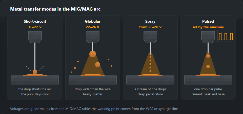
How the molten wire crosses into the pool decides penetration, spatter and which positions you can weld in. In MAG 135 welding — solid wire under an active gas, process number from ISO 4063 — there are four modes. Three are set with the same two knobs, wire feed speed and voltage; the fourth needs a pulsed power source. The voltages below come from the settings table further down the page.
Short arc (dip transfer)
The droplet on the wire tip touches the pool and shorts the circuit, the arc goes out, the short-circuit current pinches the bridge, surface tension pulls the droplet in and the arc reignites — 50 to 200 times a second at 16–22 V. The pool stays small and cool: sheet up to 3 mm, root runs, gaps, every position including vertical-up (PF) and overhead. Gas: M21 mix or pure CO₂ (more spatter, deeper penetration). By ear a steady, rapid crackle; on the plate a narrow, slightly convex bead. The weakness is lack of sidewall fusion on thicker plate. If the machine has an inductance knob, more inductance gives a softer arc and a wetter pool with less spatter; less gives a crisper, colder arc.
Globular transfer
At 22–26 V the droplet grows bigger than the wire diameter, wobbles on the tip and falls irregularly, partly with a short circuit that bursts it. In pure CO₂ the transfer above short arc stays globular almost everywhere. By ear: irregular pops and crackling; on the plate: coarse spatter balls beside the weld and uneven penetration. The 5–6 mm row of the settings table (22–25 V) sits right in this band. If the arc still crackles evenly, you are at the top of short arc; if it pops, back the voltage off or raise both knobs into spray. What the pool does in each mode is covered on the weld pool page.
Spray transfer
From 26–28 V and enough current the droplet detaches before it reaches the pool: fine droplets fly in a stream along the wire axis, with no short circuits. This only happens in an argon-rich gas — in the wire table, Ar + 15–20 % CO₂; pure CO₂ will not spray. Use: metal from 5 mm, flat PA, and PB for fillets; fill and cap passes. Deep penetration, a smooth bead with almost no spatter, and a steady hiss — which is the correct sound here. Out of position, the big pool runs.
Pulsed transfer
The source switches between a background current that just keeps the arc alive and a peak above the spray threshold that detaches exactly one droplet. Average current stays low: spray-like transfer with heat suitable for positional work and thin sheet. You do not set a voltage — the machine runs a synergic curve for the metal, wire and gas; you choose wire feed or thickness and trim the arc length. By ear an even hum; on the plate a regular ripple with no spatter.

Moving from one mode to another
- Short arc → spray: raise wire feed and voltage together in small steps. The crackle turns irregular (get through the globular band quickly), then becomes a steady hiss and the spatter stops. If it keeps popping, the gas has too much CO₂ or the current is too low for the wire diameter.
- Back down, say for a vertical weld: lower both knobs together until the crackle is even again.
| Transfer | Voltage | What it is like | Where it is used |
|---|---|---|---|
| Short-circuit | 16–22 V | The arc dies and restrikes 50–200 times a second, the pool stays cool | Thin metal, the weld root, every position |
| Globular | 22–26 V | Heavy spatter, droplets larger than the wire — the transition zone between short arc and spray | Mid thicknesses (5–6 mm) on CO₂ and mixes below the spray threshold current; in production pulsed MIG increasingly replaces it |
| Spray | from 26–28 V | A steady stream of fine droplets, almost no spatter, deep penetration | Metal from 5 mm, flat position, argon mixtures |
| Pulsed | set by the machine | One droplet per pulse, low heat input | Stainless, aluminium, thin metal — it demands a good machine |
The gas
Argon with 15–25 % CO₂ — group M21 of EN ISO 14175, such as 82/18 — covers most steel work. More CO₂ means deeper penetration and more spatter; less means a cleaner face and access to spray transfer. Pure CO₂ is cheap, penetrates well and spatters. Stainless takes argon with 2 % CO₂ or oxygen; aluminium takes pure argon. The gas selection calculator gives the mixture with its EN ISO 14175 designation.
Flow rate is 10 to 16 l/min. Turning it higher does not improve matters past a point: the jet goes turbulent and starts pulling air in. Porosity is more often a draught, a leaking hose or a spatter-blocked nozzle than a low setting.
| Metal | Wire | Gas |
|---|---|---|
| Carbon steel | ER70S-6, G3Si1 | CO₂ or Ar + 15–20 % CO₂ |
| Stainless steel | ER308L, ER316L, ER309L | Ar + 2 % CO₂ or Ar + 2 % O₂ |
| Aluminium | ER4043 (Si), ER5356 (Mg) | Ar 99.99, Ar + He for thick sections |
| Galvanised steel | ER70S-6, flux-cored | Ar + CO₂, extraction is a must |
A starting point that works
For 1.2 mm wire in Ar/18 CO₂ on 5 mm steel: about 220 A, which is roughly 6.5 m/min of wire, at 24 to 25 V, stick-out 12 mm. That is the top of short arc, on the edge of the globular band, so listen to the arc: it should still sound like frying bacon, a steady rapid crackle. A slow irregular popping means the voltage is too high for the wire speed; a harsh stuttering means the opposite.

What goes wrong
Feeding problems dominate the fault list: a worn liner, a contact tip burnt oval, roll pressure set by feel, or a torch coiled into a loop on the floor. Symptoms and cures are in wire feeding problems. The second most common complaint, lack of fusion in short arc mode, is a technique and heat problem rather than a machine one — see lack of fusion and penetration.
Settings by thickness
| Thickness, mm | Wire, mm | Current, A | Voltage, V | Gas, l/min |
|---|---|---|---|---|
| 0.8–1.0 | 0.6–0.8 | 40–70 | 15–17 | 8–10 |
| 1.5–2 | 0.8 | 70–110 | 17–19 | 10–12 |
| 3 | 0.8–1.0 | 110–150 | 19–21 | 12–14 |
| 5–6 | 1.0–1.2 | 160–220 | 22–25 | 14–16 |
| 8–10 | 1.2 | 220–280 | 26–29 | 16–18 |
| 12+ | 1.2–1.6 | 280–350 | 29–32 | 18–20 |
The full chart with wire feed speed, TIG, thin sheet and box section: MIG/MAG and TIG settings.
Symptoms and what to check
| Symptom | What to check |
|---|---|
| Pores in the weld | Gas flow, a blocked nozzle, a draught, rust and paint on the edge |
| The wire pops and snaps | A worn contact tip, roller pressure, a clogged liner |
| The wire feeds in jerks | A liner for another diameter, a kinked hose, the wrong roller groove |
| Heavy spatter | Voltage too low, pure CO₂, too much stick-out |
| Burn-through on thin metal | Current too high — weld in tacks or break the arc |
Torch technique: push or drag
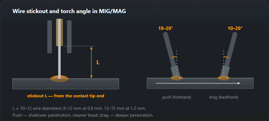
The torch leans 10–20° from vertical along the travel direction, as in the stickout drawing above. Pushing (forehand) aims the arc at cold metal ahead of the pool: shallower penetration, a wider, flatter bead and a clear view of the joint — for thin sheet and cap passes. Dragging (backhand) blows the arc into the pool: deeper, narrower penetration and a taller bead; flux-cored wire with slag is always dragged. Beyond 20° the gas jet tips over and pulls in air — porosity. Across the joint: square to the plate on a butt weld, on the bisector of the angle on a fillet, and slightly towards the thicker part when thicknesses differ.
Stickout: 10–15 wire diameters, so 10–15 mm for 1.0 mm wire and 12–18 mm for 1.2 mm. Longer stickout at the same feed means less current, shallower penetration, weaker shielding and more spatter; shorter means spatter in the nozzle and a burnt tip. If the stickout wanders, so does bead width.
Weaving: MAG is usually run as a straight stringer. Weave for wide caps and vertical-up: in PF a small triangle, pausing at the edges and not in the middle — otherwise you get a hump in the centre and undercut at the toes. The full vertical technique is in vertical-up welding.
Wire feed and voltage as a pair
Wire feed is current, voltage is arc length; in every row of the settings table both climb together. The order is always the same: feed by thickness, voltage on scrap from low to high until the crackle is even, travel speed last. What a mismatched pair sounds and looks like is in the bead-and-sound list after the worked example.
Worked example: 3 mm and 10 mm plate
3 mm steel, 1.0 mm wire, M21. The 3 mm row gives 110–150 A, 19–21 V and 12–14 l/min. Mid-range 130 A — by the wire feed calculator’s formula 5.5 m/min — at 20 V and 13 l/min, stickout 10–15 mm. 20 V sits in the short-arc band, so any position works. For vertical-up take the bottom of the row: 110 A = 4.5 m/min at 19 V. Thinner still: welding thin sheet.
10 mm steel, fillet in PA/PB, 1.2 mm wire, M21. The 8–10 mm row: 220–280 A, 26–29 V, 16–18 l/min. Mid-range 250 A = 7.5 m/min at 27–28 V, stickout 12–18 mm — above the spray threshold, and in M21 you get spray; in pure CO₂ the same settings would run globular. The same weld vertical: several passes in short arc up to 22 V, or pulse.
Reading the bead and the sound
- Harsh stutter, torch kicks back: more voltage or less wire.
- Hissing at short-arc settings: less voltage (in spray, a hiss is normal).
- Pops and coarse spatter balls: globular band or too much CO₂.
- Tall, narrow bead sitting on the plate: too little voltage or too fast — expect lack of fusion.
- Groove along the toe: too much voltage, too steep an angle, dwelling mid-weave — see undercut.
- Bead wide, then narrow: uneven travel speed or stickout.
Practice exercises
- Voltage ladder: five stringers on 3 mm plate in PA with the first example’s settings, one voltage step per bead. Goal: find the bead with an even crackle and flat toes again without trial runs.
- Push versus drag: two beads, cut across, grind the section — the dragged one must be visibly deeper.
- Stickout: 10 mm against twice that; compare spatter and width.
- Fillet break test: a 3 mm T-joint in PB, then knock the upright over until the weld breaks. Fused right into the corner is a pass; a smooth strip at the root is lack of fusion.
- Spray threshold: 10 mm plate, M21, raise both knobs until the crackle turns to a hiss, and note the values for your machine.
Frequently asked questions
What is the difference between MIG and MAG?
Only the gas. MIG uses an inert gas — argon or argon-helium — and is what you use on aluminium and copper. MAG uses an active mixture containing CO₂ or oxygen and is what you use on steel. The equipment and the technique are the same, which is why everyone says "MIG" for both and the plate on the machine says MIG/MAG.
Push or drag?
Pushing gives a flatter, wider bead with less penetration and a better view of the joint; dragging gives more penetration and a narrower bead. On steel with solid wire either works — pick one and stay consistent. With flux-cored wire you drag, because the slag has to end up behind the pool.
Why is the weld porous outdoors?
Wind. A breeze of about 2 m/s is enough to strip the gas shield — AWS D1.1 allows gas-shielded processes no more than 8 km/h (about 2.2 m/s) at the weld — and that is a light draught through an open door. Screen the joint, or switch to MMA or self-shielded flux-cored wire, which carry their protection with them.
What does MAG 135 mean?
135 is the process number in ISO 4063: MAG welding with solid wire in an active gas. The same group holds 131 (MIG with solid wire in inert gas), 136 (MAG with flux-cored wire) and 138 (MAG with metal-cored wire). The number goes on the WPS, the welder’s certificate and the drawing. Machine and torch are the same for 135, 136 and 138; the wire changes and often the gas.
Which transfer mode for thin sheet and out-of-position work?
Short arc (16–22 V) or pulse. Both keep the pool small enough for vertical-up and overhead. Spray is for metal from 5 mm in the flat position and for fillets in PB; out of position its pool runs.
Why does the arc hiss instead of crackle?
At short-arc settings a hiss means the voltage is too high for the wire feed: the arc is long and the drops are big. Turn the voltage down or add wire. In spray transfer, on the other hand, a steady hiss with no crackle is exactly the right sound.
Updated: