Undercut: causes, limits and repair
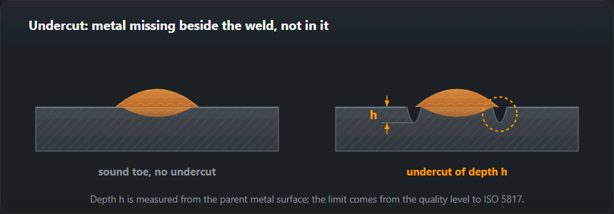
A groove melted into the parent metal along the toe of the weld and left unfilled. Easy to see, easy to measure, and more serious than it looks.

Why it matters
Two reasons. It removes section — a 1 mm groove in a 6 mm plate is a sixth of the thickness gone. And it puts a sharp notch exactly at the weld toe, which is where bending stress peaks and where fatigue cracks start anyway. Under static load undercut is a nuisance; under fatigue load it is the crack initiation site.
What causes it
Current too high. The commonest cause by far. The arc digs into the parent metal faster than the filler can fill the groove behind it.
Arc too long. A long arc spreads and washes the toes without depositing there.
Travel speed too high. The pool does not have time to flow out to the edges before it freezes.
Wrong torch or electrode angle. Especially on a fillet in the horizontal position, where too much angle towards the vertical plate melts its edge and lets gravity pull the metal down and away.
Weaving badly. Pausing in the middle and sweeping quickly at the edges is exactly backwards. The pause belongs at the edges of the weave, where it lets the pool fill the toe.
Fixing the technique
Drop the current 10 % and see what changes; it is the fastest diagnostic. Shorten the arc. Slow down. On a horizontal fillet, aim the arc more at the bottom plate and let the pool wash up to the vertical one, rather than pointing into the corner.
Undercut on the last run of a multi-run weld is often a cap-run problem alone: the fill runs were fine and the cap was made too hot and too fast because the joint was nearly finished.

Repair
Grind the groove out to clean metal with a smooth transition — no sharp step at the ends of the ground area. Then a stringer run at reduced current, and blend the toe afterwards. Grinding alone, without adding metal, is only acceptable if the remaining thickness still satisfies the drawing, and that is a decision for the inspector rather than the welder.
Related shape defects with the same root causes are collected in the defect catalogue, group 500.
Causes and quality levels
| Cause | What happens | What to do |
|---|---|---|
| Current too high | The arc eats into the edge deeper than it should | Drop it by 10–20 A and check against the calculator |
| Travelling too fast | The pool has no time to flow out to the edge | Slow down and watch the bead width |
| Long arc | The heated spot is wider than the pool | Hold the arc about one electrode diameter long |
| Wrong electrode angle | The arc hits the edge instead of the pool | Tilt 10–15° into the direction of travel, no sideways lean |
| No pause at the edge | When weaving, the pool never fills the edge | Dwell a fraction of a second at each end of the weave |
| Electrode too large | The pool is wider than this thickness needs | Take a smaller diameter and run two passes |
| Level to ISO 5817 | How undercut is treated | Where it applies |
|---|---|---|
| B | The tightest limits on depth | Pressure vessels, dynamic loads |
| C | Moderate tolerances | Most structural steelwork |
| D | The loosest | Non-critical work, static loads |
Types of undercut in ISO 6520-1
On an inspection report undercut carries a number from group 501, and the last digit says what it looks like:
- 5011 — continuous undercut. A groove over a long length with no break — usually a constant parameter fault: too much current or too fast a travel speed along the whole weld.
- 5012 — intermittent undercut. Short lengths with gaps — more often hand technique: an uneven weave, a changing angle, welding round obstructions.
- 5013 — shrinkage groove. Undercut on either side of the root bead, on the penetration side, caused by shrinkage of the root run — not to be confused with undercut on the cap.
- 5014 — inter-run undercut. A groove between neighbouring capping runs in a multi-run weld.
The other shape imperfections are in the ISO 6520-1 imperfection numbers table.
Permitted undercut: figures for common thicknesses
ISO 5817 limits undercut depth with a formula based on thickness t and a cap: level B 0.05·t, max 0.5 mm; level C 0.1·t, max 0.5 mm; level D 0.2·t, max 1 mm. It also requires a smooth transition — a sharp groove does not become acceptable just because it is shallow. In figures (bold where the cap applies):
| Thickness t, mm | B — stringent | C — intermediate | D — moderate |
|---|---|---|---|
| 4 | 0.2 mm | 0.4 mm | 0.8 mm |
| 5 | 0.25 mm | 0.5 mm | 1 mm |
| 6 | 0.3 mm | 0.5 mm | 1 mm |
| 8 | 0.4 mm | 0.5 mm | 1 mm |
| 10 | 0.5 mm | 0.5 mm | 1 mm |
| 12 | 0.5 mm | 0.5 mm | 1 mm |
| 16 | 0.5 mm | 0.5 mm | 1 mm |
| 20 | 0.5 mm | 0.5 mm | 1 mm |
The practical conclusion: from 10 mm plate upwards levels B and C share the same 0.5 mm limit, and at D the limit never rises above 1 mm, even on 40 mm plate. On heavy sections undercut has to be kept just as shallow as on thin ones. The value for any thickness is in the ISO 5817 acceptance calculator.
Two examples from inspection
Fillet weld, 8 mm plate, level C
0.6 mm is measured along the upper toe. Limit: 0.1·8 = 0.8 mm, but the cap is 0.5 mm — the weld is rejectable. Grinding alone does little, because grinding deepens the groove; a thin run at reduced current is needed, then the toe is blended. The same reading at level D (limit 1 mm) would be acceptable.
Butt weld, 5 mm plate, level B
Limit 0.05·5 = 0.25 mm. That is close to what an ordinary weld gauge can resolve — at level B on thin plate it makes more sense to prevent undercut than to argue afterwards over tenths of a millimetre. Lower current on the cap and a short pause at the edges of the weave help.
Why undercut favours certain positions
In the horizontal position on a vertical face (PC) and in a horizontal fillet (PB) the pool runs down under its own weight, so the upper toe is melted but left unfilled. In the vertical-up position (PF) undercut usually appears on both toes when the welder speeds up through the middle of the weave and does not pause at the edges. Overhead (PE) the cap tends to sag, leaving the toes hungry. Position designations and how they affect settings are on the welding positions page.
Mistakes when assessing and repairing undercut
- Measuring from the weld face instead of the plate. Depth is taken from the parent metal surface. Zeroing on the face gives a meaningless figure.
- Confusing it with root concavity. A groove on the penetration side, in the middle of the root, is 515 — a different formula; at level C on 8 mm the limit is 0.8 mm, not 0.5 mm.
- Grinding until the groove disappears. Taking the plate down to the bottom of the undercut reduces the thickness; whether that is allowed is for the drawing and the inspector to decide, not the grinder.
- Not recording it. Undercut that is “within limits” is still recorded with its depth — at the next inspection you can see whether the process is drifting. The VT report generator makes that quick.
Frequently asked questions
How much undercut is allowed?
It depends on the quality level and the thickness. Level B allows 0.05·t up to 0.5 mm, level C 0.1·t up to 0.5 mm, level D 0.2·t up to 1 mm — and there are conditions on smoothness. The acceptance calculator does the arithmetic for your thickness.
Can undercut be filled in with a small run?
Sometimes, and it must be agreed first: on many contracts repair welding needs its own approved procedure. Where it is allowed, the groove is ground clean and a small stringer run is laid with reduced current — never a quick dab with the same settings that caused it.
What is the difference between undercut 5011, 5012 and 5014?
5011 is continuous undercut — the groove runs along the toe without a break. 5012 is intermittent: short lengths with sound toe between them. 5014 is inter-run undercut, a groove between neighbouring runs of a multi-run weld. ISO 5817 assesses the depth of 5011 and 5012 with the same formula.
How do I measure undercut depth?
With the depth pointer of a weld gauge, zeroed on undisturbed plate beside the weld — not on the weld face. Measure at the deepest point after removing slag and spatter. In a very narrow groove the tip cannot reach the bottom and the gauge reads short; a replica or a macro section then settles it.
Updated: