Horizontal welding: how to avoid undercut along the top edge
A horizontal weld runs across a vertical surface. The pool is pulled downwards, so the upper edge ends up undercut and the lower one gets an overlap. The whole job is to prop the pool up with the arc.
Where this position turns up
On tanks and pipes erected upright, on shell courses, on columns and anywhere the part cannot be laid flat. On pipework it matches the 2G setup: the pipe stands vertical and the weld runs round the circumference.
How to run it
Point the electrode slightly upwards, 5–15° above horizontal: the arc then holds the pool from below and stops it running. Keep the arc short and the beads narrow, with no wide weaving — every wide weave turns into undercut along the top. Take the current 10 % below the flat position (the calculator multiplies the range by 0.9).
Guide settings for a rutile electrode, current 10 % below the flat position
| Thickness, mm | Electrode diameter, mm | Current, A |
|---|---|---|
| 1–2 | 1.6 | 35–55 |
| 1.5–3 | 2.0 | 45–70 |
| 2–4 | 2.5 | 65–90 |
| 3–5 | 3.0 | 70–115 |
| 3–6 | 3.2 | 80–125 |
| 6–12 | 4.0 | 115–170 |
| 10–20 | 5.0 | 160–225 |
| 16+ | 6.0 | 205–290 |
Electrode angles and current: a worked example
Two angles matter in a horizontal weld. Work angle — the electrode points 5–15° above horizontal so the arc holds the pool up from below. Travel angle — 10–15° in the direction of travel, as in other positions. While filling, the aim changes from bead to bead: the lower beads are aimed more at the lower plate, the upper ones at the previous bead and the upper edge — never straight at the upper face, which burns away.
Current. The PC position factor is ×0.9, i.e. 10 % less than flat — that is how the table on this page and the current calculator work. For a 3.2 mm electrode: flat 90–140 A, middle 115 A; in PC 80–125 A, middle 105 A. For 2.5 mm the PC band is 65–90 A (middle 75 A), for 4.0 mm 115–170 A (middle 145 A). Start in the middle and adjust in 5 A steps: undercut on the upper edge — less; a tall bead that does not wet the plate — more.
Arc length. 0.8–1.0 × electrode diameter: 2.6–3.2 mm for 3.2 mm, 2.0–2.5 mm for 2.5 mm. In PC stay at the short end — a long arc is the first cause of undercut at the top.
Diameter. The table lists bands for thick electrodes too, but a large pool in the horizontal position runs down onto the lower plate. Narrow stringers are easier with 2.5–3.2 mm; a thicker rod makes sense only for the lower fill beads on heavy plate.
Multi-run welds
Lay the runs as ledges from the bottom up: the first against the lower edge, each following one resting on the previous and overlapping it by about a third. That stacking supports the pool and keeps it from sagging. At every break, clean the slag off the boundary between runs — that is exactly where lack of fusion sits.
Joint preparation and bead sequence for a PC butt weld
In the horizontal position it is common to bevel only the upper plate (single bevel, ½V) and leave the lower one square: its edge acts as a shelf that carries the first beads. From the groove table for ½V: angle 45–55°, root face 1–3 mm, gap 1–3 mm. For an ordinary single V: 50–70°, root face 1–2 mm, gap 1–4 mm. Exact figures for your thickness come from the groove calculator.

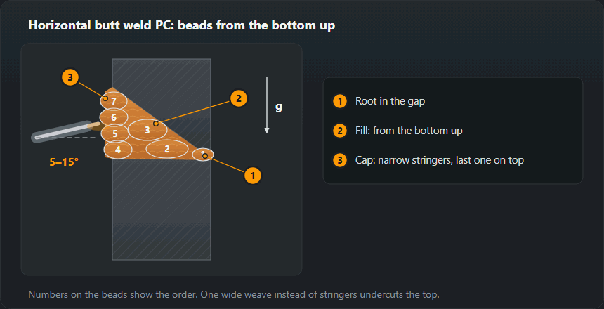
- Root. A 2.5 mm electrode at the low end of the band (65–90 A), the arc into the gap and slightly towards the lower plate. Check the back side: penetration should be even along the whole length.
- Fill from the bottom. The first fill bead goes against the lower plate, the second on top of it and against the bevel. Each bead straight or with a minimal weave.
- Cap. Several narrow stringers from the lower edge of the groove upwards. The last one, along the upper edge, runs a little faster with a short arc — it decides whether undercut is left.
- Cleaning. Chip the slag after every bead, especially in the notch between the bead and the upper face — that is where inclusions are usually left.
MIG/MAG in the PC position
With a MIG torch the principle is the same: torch pointed slightly up, narrow beads from the bottom. From the MIG/MAG settings table: 3 mm plate — 0.8–1.0 mm wire, 110–150 A, 19–21 V; 5–6 mm — 1.0–1.2 mm wire, 160–220 A, 22–25 V. In the horizontal position stay nearer the lower row and add passes: a large, fluid pool runs down onto the lower plate. More on settings in the MIG/MAG guide.
Typical defects
Undercut along the top edge is defect number one here: it comes from a long arc, too much current and wide weaving. An overlap at the bottom means you travelled too slowly. Lack of fusion between runs shows up where the next bead was placed too low or laid over unclean slag.
Reading a horizontal weld and what to change
- Undercut on the upper edge — a groove along the upper toe of the cap. Under ISO 5817, on 10 mm plate it is limited to 0.5 mm at level B, 0.5 mm at C and 1 mm at D. Fix: shorter arc, 5–10 A less, a narrower last stringer.
- Overlap on the lower plate — metal rolled onto the plate without fusing, with a sharp toe angle. Travel too slow or electrode aimed too far down.
- Sagging bead — the cap droops, the ripples slant. Weave too wide or electrode too thick; split the cap into more stringers.
- Lack of fusion between beads — visible only in a section or a break test. The next bead was placed too low or over slag; aim at the upper edge of the previous bead.
Designation and qualification
The horizontal position is PC to EN ISO 6947, 2G on pipe. A qualification passed in PC covers neither PF nor PE: they are separate positions with separate test pieces. The range follows from the test details.
Practice and the PC qualification
- Pad on a vertical plate. 8–10 mm plate standing upright, horizontal stringers from the bottom up, each resting on the one below. Goal: even width, no groove above the bead.
- ½V joint with backing. Only the upper plate bevelled, a backing strip behind. Fill and cap in narrow stringers as in the diagram above.
- Open-root joint. Root with full penetration, then a break test or a section: fused root and no slag against the upper face.
- Vertical pipe, 2G. The same technique round the circumference — pipe set-ups are described in pipe welding positions.
A PC test under EN ISO 9606-1 covers PA, PB, PC. It does not cover vertical (PF gives PA, PB, PF) or overhead (PE gives PA, PB, PC, PD, PE). All positions side by side are in the welding positions overview, and the range for your own data comes from the qualification range calculator.
Frequently asked questions
Why does a horizontal weld undercut the top edge?
Because the pool sags and leaves the edge bare, and the arc burns it away. The cure is always the same: a shorter arc, less current, a narrower bead and the electrode angled slightly upwards.
How are the runs stacked in a multi-run weld?
As ledges from the bottom up: the first against the lower edge, each following one resting on the previous and overlapping it by about a third.
Does a PC qualification cover vertical and overhead?
No. Under EN ISO 9606-1 a PC test covers PA, PB and PC; PF and PE are separate tests. It only works the other way for PE: a PE test also covers PC.
What current for a 3.2 mm electrode in the PC position?
Horizontal takes ×0.9 of the flat value: 80–125 A, start at about 105 A. Flat, the same electrode takes 90–140 A. Adjust in 5 A steps by the upper edge: undercut — less, tall bead — more.
What electrode angle for a horizontal weld?
5–15° above horizontal and 10–15° in the direction of travel, so the arc holds the pool up from below. Aim the lower beads at the lower plate and the upper ones at the previous bead, never straight at the upper face.
Does a PC qualification cover PB?
As a position, yes: on the EN ISO 9606-1 coverage table a PC test covers PA, PB, PC. Whether it also covers fillet welds depends on the joint type on the certificate (BW or FW), not on the position. PF and PE are not covered.
Updated: