How many amps for a stick electrode: current by diameter and position
The first setting anyone makes, and the one that decides how the rest of the weld behaves. The calculator starts from the diameter and then corrects for the position, the coating and the plate thickness.
Short answer
Flat position: 2.5 mm — 70–100 A, 3.2 mm — 90–140 A, 4.0 mm — 130–190 A. The current calculator adds the correction for position and coating and checks the diameter against the thickness.

How it is worked out
The base figure is the flat-position range for the core diameter in the table
below — roughly I = (30…40) · d, a little more per millimetre on
thick rods. The coating shifts it: a basic rod gets +5 %, because its
coating needs more energy to melt and gives a stiffer arc; a cellulosic one
−5 %.
Two corrections follow. Position: −10 % for horizontal, −15 % for vertical, −20 % for overhead. Thickness: the calculator does not cap the current, but it checks whether the diameter suits the plate and names a better one if it does not.
The base range in the flat position
| Diameter, mm | Current, A | Middle, A | Material thickness, mm |
|---|---|---|---|
| 1.6 | 40–60 | 50 | 1–2 |
| 2.0 | 50–80 | 65 | 1.5–3 |
| 2.5 | 70–100 | 85 | 2–4 |
| 3.0 | 80–130 | 105 | 3–5 |
| 3.2 | 90–140 | 115 | 3–6 |
| 4.0 | 130–190 | 160 | 6–12 |
| 5.0 | 180–250 | 210 | 10–20 |
| 6.0 | 230–320 | 270 | from 16 |
Checking it at the arc
The number is a starting point; the weld tells you the rest — the signs are in the table below and in the run on scrap further down.
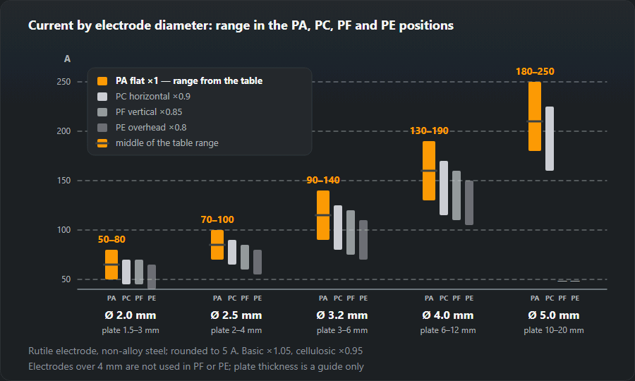
If you need a table to pin on the wall rather than a calculator, the same figures are laid out in current versus electrode diameter.
How to tell the current is wrong
| Symptom | Cause | What to do |
|---|---|---|
| The electrode sticks, the arc goes out | Current too low | Add 10–15 A |
| Narrow, high bead with no penetration | Current too low | Add current or slow the travel |
| Heavy spatter, the electrode glows red | Current too high | Take off 10–20 A, use a thinner electrode |
| Burn-through, undercut along the edges | Current too high | Drop the current, dwell less on the edge |
| The pool runs in the vertical | Current too high for the position | Cut it by 15 % against the flat position |
What current for a 2, 2.5, 3, 3.2 and 4 mm rod
Below are the same figures the calculator gives, for a rutile rod. A basic coating adds 5 %, a cellulosic one takes 5 % off.
2 mm rod
Flat 50–80 A, middle 65 A; vertical 45–70 A; overhead 40–65 A. Material 1.5–3 mm: box section, angle, thin sheet. With a 2 mm rod you see clearly how thin material drops through with an extra 10 A, so start in the middle.
2.5 mm rod (3/32")
Flat 70–100 A, middle 85 A; horizontal 65–90 A; vertical 60–85 A; overhead 55–80 A. A basic rod in the flat: 75–105 A. Material 2–4 mm. The most common size for home inverters and positional work.
3 and 3.2 mm rods (1/8")
A 3 mm rod in the flat: 80–130 A, middle 105 A; vertical 70–110 A. The 3.2 mm range sits higher: flat 90–140 A, horizontal 80–125 A, vertical 75–120 A, overhead 70–110 A; a basic 3.2 in the flat 95–145 A. Material 3–6 mm.
4 mm rod (5/32")
Flat 130–190 A, middle 160 A; horizontal 115–170 A; vertical 110–160 A; overhead 105–150 A; basic in the flat 135–200 A. Material 6–12 mm. Check that the set holds that current at the duty cycle you need: a 160 A home inverter runs a 4 mm rod at its limit.
5 mm rod
Flat 180–250 A, horizontal 160–225 A. Nobody runs a 5 mm rod vertical or overhead: the pool is too big. Material 10–20 mm, fill runs.

Setting-up examples
- A gate in 2 mm wall box section. 2.0 mm rutile rod. Horizontal welds in the flat about 65 A (range 50–80), vertical joints on the uprights about 55 A (45–70).
- An 8 mm plate butt with basic rods. Root with 3.2 mm, range 95–145 A, kept towards the bottom for the root. Fill with 4 mm at 135–200 A; the calculator suggests 170 A.
- An overhead weld on 6 mm plate. Basic 3.2 mm at 75–120 A, middle about 95 A. Keep the arc short.
- A horizontal weld on a wall, 5 mm plate. Rutile 3.2 mm at 80–125 A, about 105 A.
Five minutes on scrap
- Set the current the calculator suggests — the middle of the range.
- Take scrap of the same thickness and run a bead in the same position the real weld will be in.
- Look at the bead and listen to the arc: an even hiss and a bead that blends smoothly into the plate mean the current is right.
- Sticking, a narrow humped bead — add 10–15 A. Spatter, undercut, the rod glowing red — take off 10–20 A.
- Burn a whole rod: if the last third glows red and the coating falls off, the current is at the top limit even if the start looked fine.
Too much and too little current: what it looks like
Too little. The arc is quiet, keeps breaking, the rod sticks. The bead is tall and narrow, sits on the surface and is not fused at the toes; slag gets folded into the metal and is hard to remove. Cut it open and the root is not penetrated.
Too much. The arc roars, spatter flies a long way, the toes are undercut and thin plate burns through. The rod glows towards the end and the coating cracks and drops off before the core is used up. On a vertical the pool runs.
Once the weld is running, the electrode consumption calculator tells you how many rods and kilograms the job takes. If the rod sticks at the right current, the causes are worked through in why the electrode keeps sticking.
Frequently asked questions
Where does the 30–40 A per millimetre rule come from?
From the current density the coating and the core wire can take. Below that the coating does not burn evenly and the arc keeps going out; above it the core overheats, the coating cracks off in the last third of the electrode and the arc starts wandering. The band is empirical but it has held for decades across manufacturers.
Why does the current drop for vertical and overhead work?
Because gravity stops helping. In the flat position surface tension and gravity both hold the pool in the joint; vertical-up and overhead leave only surface tension, so the pool has to be kept small — and a smaller pool means less current, 15 % below the flat figure for vertical and 20 % for overhead.
The machine dial and the actual current disagree. Which do I trust?
The measurement. Dials on cheaper inverters are marked at no load and drift under a long cable run; a clamp meter on the welding lead settles the question in ten seconds. If the reading is far below the dial, check the cable cross-section before blaming the machine.
What amperage for a 2.5 mm (3/32") rod?
Rutile in the flat: 70–100 A, middle about 85 A. Vertical: 60–85 A; overhead: 55–80 A. A basic 2.5 in the flat: 75–105 A. It is the rod for 2–4 mm material.
What amperage for a 2 mm rod?
Flat: 50–80 A, middle about 65 A. Vertical: 45–70 A; overhead: 40–65 A. A 2 mm rod welds 1.5–3 mm material: box section, thin sheet, patches.
Can I run a 3.2 mm rod at 70 A?
Not in the flat: the bottom of the range for 3.2 mm is 90 A, and below it the rod sticks and the bead comes out narrow with no penetration. Even overhead the range starts at 70 A. If the machine will not give more, use a 2.5 mm rod.
Updated: