Table: welding current, electrode diameter and plate thickness
One table for stick welding: from the thickness of the part to the electrode diameter and the current range in every position. Figures are for rutile electrodes on low-carbon steel.
Short answer
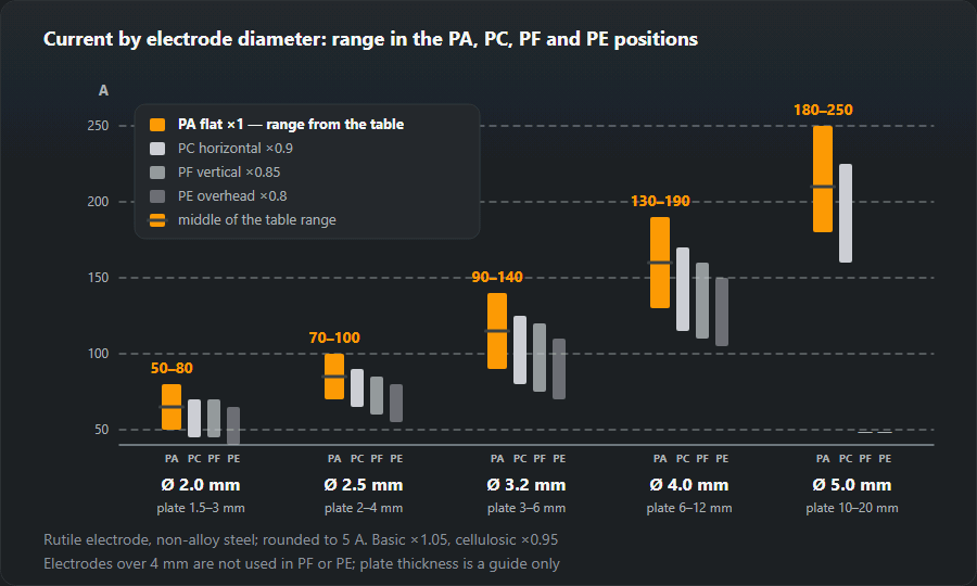
Flat position: 2.5 mm — 70–100 A, 3.2 mm — 90–140 A, 4.0 mm — 130–190 A. The current calculator adds the correction for position and coating and checks the diameter against the thickness.

The main table
| Thickness, mm | Electrode, mm | Flat, A | Horizontal, A | Vertical, A | Overhead, A |
|---|---|---|---|---|---|
| 1–2 | 1.6 | 40–60 | 35–55 | 35–50 | 30–50 |
| 1.5–3 | 2.0 | 50–80 | 45–70 | 45–70 | 40–65 |
| 2–4 | 2.5 | 70–100 | 65–90 | 60–85 | 55–80 |
| 3–5 | 3.0 | 80–130 | 70–115 | 70–110 | 65–105 |
| 3–6 | 3.2 | 90–140 | 80–125 | 75–120 | 70–110 |
| 6–12 | 4.0 | 130–190 | 115–170 | 110–160 | 105–150 |
| 10–20 | 5.0 | 180–250 | 160–225 | — | — |
| from 16 | 6.0 | 230–320 | 205–290 | — | — |
Electrodes of 5 and 6 mm are effectively never used vertically or overhead: the pool becomes too large to hold. In those positions the electrode goes no thicker than 4 mm and the joint is filled with several runs.

Correction for the coating
| Coating | Typical brands | Factor | Current |
|---|---|---|---|
| Rutile | OK 46.00, ER 146 | 1.00 | AC / DC± |
| Basic | OK 48.00, EB 150 | 1.05 | DC+ |
| Cellulosic | OK 22.45 | 0.95 | DC+ / AC |
| Acid | — | 1.00 | AC / DC |
Work it out for your case
The table gives a range; the current calculator applies the corrections for position and coating straight away and checks whether the diameter suits your thickness.
Reading the table: three examples
The order never changes: material thickness → electrode diameter → position column → coating correction. Where you sit inside the range depends on the details — the gap, the number of runs, how hot the part already is.
- 5 mm plate, flat, rutile. The thickness falls in the 3–6 mm row — a 3.2 mm rod at 90–140 A. Start in the middle, about 115 A.
- 4 mm angle, vertical weld. Thin material on a vertical takes a thinner rod: 2.5 mm, “Vertical” column — 60–85 A. A 3.2 will do it too, but the pool is harder to hold.
- 10 mm beam, basic rod. The 6–12 mm row — a 4 mm rod, 130–190 A in the flat; the 1.05 correction for a basic coating gives 135–200 A. An overhead weld on the same beam — 4 mm at 110–160 A, or a 3.2 in several runs.
When the thickness falls between rows
The rows overlap on purpose: one thickness can be welded properly with two diameters. Position and gap decide.
- 3 mm is 2.5 (2–4 mm), 3.0 and 3.2 at once. Flat with no gap — a 3 mm rod, quicker and smoother. Vertical, overhead or a noticeable gap — 2.5: a smaller pool and less risk of burning through.
- 6 mm is the border between 3.2 and 4.0. A flat fillet goes in with a 4 mm rod in one run; a vertical is calmer with a 3.2.
- 10–12 mm is 4.0 and 5.0 territory. A 5 mm rod is used only flat and horizontal; the root goes in with a thinner rod anyway and the fill with the thick one.
Bottom or top of the range
The range in the table is wide — 50–60 A for 3–4 mm rods — and the weld behaves differently across it.
- Towards the bottom: root run, a wider gap than usual, a thin edge, a part already hot from earlier runs.
- Towards the top: fill runs, a fillet on thick plate in the flat, a cold heavy part that pulls the heat away.
- How to correct: the rod sticks and the bead is narrow — add 10–15 A; lots of spatter and undercut — take off 10–20 A. The full symptom table is on the current calculator page.
The amps-per-millimetre rule and why the table is better
The quick estimate I ≈ (30…40) · d works well in the middle of the
series: for 3.2 mm it gives 96–128 A, inside the table's 90–140 A. At the
ends it goes wrong: for a 4 mm rod it gives 120–160 A while the table goes
up to 190 A, and for 1.6 mm its upper figure, 64 A, is outside the table's
40–60 A. The rule is for a guess at the machine; the table is for setting up.
Applying the coating correction
The factor multiplies both ends of the range. A 3.2 mm rod in the flat: rutile 90–140 A, basic (×1.05) 95–145 A, cellulosic (×0.95) 85–135 A. The difference is small; the type of current matters more: basic rods want DC with the electrode positive, rutile rods run happily on AC as well. If the packet gives a different current from the table, the maker is right.
Frequently asked questions
How do I estimate the current without the table?
Around 3 mm the rule of "30 to 40 amperes per millimetre of diameter" works: a 3.2 mm rod comes out at 96–128 A, inside the table’s 90–140 A. Thin rods sit lower than the rule (1.6 mm: 40–60 A), and from 4 mm up the table runs higher — a 4 mm rod goes up to 190 A.
Is the electrode diameter chosen for the thickness or for the current?
For the thickness — that comes first. The diameter decides how much metal you can lay in one run; the current merely serves the diameter you picked. If the current will not fit inside the range, the electrode is the wrong one.
What current for a 3.2 mm (1/8") rod on a vertical?
A rutile rod: 75–120 A; a basic rod: 80–125 A. That is 15 % below the flat position — on a vertical the pool has to stay small or it runs. Start in the middle of the range and adjust by the bead.
What amperage for a 4 mm (5/32") rod?
Rutile in the flat: 130–190 A; horizontal: 115–170 A; vertical: 110–160 A; overhead: 105–150 A. A basic 4 mm rod in the flat: 135–200 A. It suits material from 6 to 12 mm thick.
Updated: