Why welds get porosity and how to tell the causes apart
Gas that was dissolved in the molten pool and did not get out before the metal froze. The most common defect there is, and the one whose cause can usually be read off the pattern of the holes.

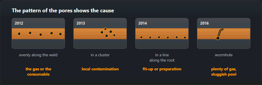
Read the pattern first
Evenly scattered along the whole weld. The shielding is inadequate everywhere: flow too low, a leaking hose, a nozzle clogged with spatter, or a draught across the bench. This is the most common case by a wide margin.
In clusters. Something local on the surface — a patch of paint, oil, primer or rust that was not removed. Clusters follow contamination, so they appear where the contamination was.
In a line along the root. The root gap is drawing air in from the other side, or the backing is contaminated. On pipe this usually means the purge failed.
Wormholes — long tubular pores. Gas escaping through metal that is already freezing, typically because the pool is too cold or is freezing too fast. Often accompanied by moisture in the consumable.
The same patterns at a glance, with two more — pores only at the start or only in the crater:
| How it looks | What it means | What to check first |
|---|---|---|
| Evenly along the whole weld | A constant source: the gas or the consumable | Gas flow, mixture composition, damp electrodes |
| In clusters, in isolated spots | Local contamination | Edge cleaning, leftover paint and primer |
| In a chain along the root | The trouble is in the fit-up or the preparation | The gap, the root face, rust in the groove |
| Single large ones at the start of the weld | No gas pre-flow | Pre-flow 0.5–2 s, purge the hose after a bottle change |
| At the end of the weld, in the crater | No post-flow | Post-flow ≈ 1 s for every 10 A of current |
| Wormholes — long channels reaching the surface | Plenty of gas and a sluggish pool | Slow down, raise the heat input, dry the material |
The five sources
Shielding gas. Flow rate, leaks, blocked nozzle, wind. The threshold for wind is low: about 2 m/s strips the shield, which is a light draught through an open door.
Moisture. In basic electrodes above all, but also in flux core and on a cold plate that has condensation on it. Basic electrodes want re-baking at 300–350 °C and then a heated quiver.
Surface contamination. Paint, primer, oil, cutting fluid, rust and — worst of all — galvanising. Zinc boils at 907 °C, well below the temperature of the pool, so it gasses off straight into the weld. Grind the coating back at least 25 mm each side of the joint.
Arc length. A long arc pulls air in past the shield, in MMA as much as in MIG. This is why porosity often disappears when a beginner is told simply to weld closer.
Nitrogen from air. The end product of every failure above: nitrogen is far more soluble in molten steel than in solid steel, so it comes out of solution as the weld freezes and has nowhere to go.
Working through it
Take them in order of cost. Look at the joint surface and clean it properly. Look at the nozzle and the gas hose. Put a flowmeter on the torch rather than trusting the regulator. Screen the bench. Only then start changing settings — and if the consumables have been open in a damp store, deal with that before anything else.
On aluminium the rules are stricter still, because hydrogen dissolves readily in molten aluminium and hardly at all in solid aluminium: see welding aluminium.
Types of porosity and their report numbers
On an inspection report porosity is not “porosity” but specific ISO 6520-1 numbers, and each one hints at a cause:
- 2011 — isolated gas pore. Spherical, inside the weld. A single pore can be a one-off, such as a drop of spatter falling from a dirty nozzle.
- 2012 — uniformly distributed porosity. Pores along the whole length: a constant gas source, usually the shielding.
- 2013 — clustered porosity. A nest in one place: local contamination, or a spot where the arc was struck and broken.
- 2014 — linear porosity. Pores in a line along the weld axis, often in the root or on the boundary between runs.
- 2016 — wormhole. An elongated tube — gas escaping through freezing metal, typically with a cold pool or moisture.
- 2017 — surface pore. Open to the outside; typical of zinc coating, paint and a strong draught.
The full list with the other cavities is in the ISO 6520-1 imperfection numbers table.
How much porosity is acceptable to ISO 5817
Porosity has the most generous limits of any imperfection — but it has limits. For a single pore the site calculator works out the permitted diameter from thickness t, with a cap:
- level B: 0.2·t, max 3 mm;
- level C: 0.3·t, max 4 mm;
- level D: 0.4·t, max 5 mm.
On 6 mm plate that gives 1.2, 1.8 and 2.4 mm, on 10 mm 2.0, 3.0 and 4.0 mm, and from 20 mm the limits sit on their caps of 3, 4 and 5 mm. Besides the single pore, the standard separately assesses clusters, linear porosity and the total pore area on the projected weld — so a weld without a single “oversized” pore can still be rejected because there are too many. The value for your thickness is in the ISO 5817 acceptance calculator.
These three limits apply to a pore inside the weld (2011). A surface pore (2017) has its own, stricter line in ISO 5817: not permitted at level B; at C 0.2·t, max 2 mm, and only above 3 mm thickness; at D 0.3·t, max 3 mm. On 10 mm plate that is a reject, 2.0 and 3.0 mm. This is the line used in visual inspection, because the eye only sees open pores.
Shielding gas flow: starting values
The gas shield is the commonest source of porosity in MIG/MAG and TIG. These are the ranges to start from:
| Process | Gas | Flow, l/min |
|---|---|---|
| MAG, steel | CO₂ or Ar+18 % CO₂ | 10–16 |
| MIG/MAG, stainless | Ar+2 % CO₂ (M12), Ar+He (I3) | 12–16 |
| MIG, aluminium | Ar, Ar+He | 14–20 |
| TIG, steel and stainless | Ar 99.99 | 6–10 |
| TIG, aluminium (AC) | Ar 99.99 | 8–12 |
| Root purging in a pipe | Ar, N₂+H₂ | 4–8 |
For a 12–16 mm nozzle with no draught. In a draught do not turn the flow up — screen the bay instead: too strong a stream turns turbulent and pulls air in by itself.
Three practical points. Measure the flow with a flow tube held against the nozzle rather than reading the regulator: the regulator shows what leaves the cylinder, not what reaches the pool. The top of the range is not “safer” — too much flow goes turbulent and draws air in. Outdoors, more gas is no substitute for a windbreak. Consumption and cylinder life per shift are worked out by the gas consumption calculator.
When the pores appear — and what it means
- Only outdoors or near an open door. A draught blows the shield away. A screen helps; more gas does not.
- Since the cylinder was changed. A different mixture from last time, moisture in the valve, or a leaking new connection.
- Only on certain plates. Primer, cutting oil, galvanising or mill scale — the material, not the settings.
Common mistakes when fighting porosity
- Turning the gas up first. Check the nozzle, the hose and the draught first — they account for most cases.
- Welding over the pores. A new run covers the pores but does not remove them; they stay on the radiograph, and gas from them can spoil the next run.
- Grinding out one surface pore and stopping. A 2017 usually has more below it. After grinding, check the bottom, ideally with penetrant.
- Changing several things at once. Swap the cylinder, nozzle and wire together and the pores go — but you do not know why, and they come back next time.
- Treating porosity as cosmetic. The pores themselves may be acceptable, but their source — moisture in a basic electrode — is also hydrogen, which in higher-strength steels causes cold cracking.
Repairing a porous weld
- Mark the extent of the porous length — visually, and with penetrant if in doubt.
- Grind or gouge out to sound metal, running a little beyond the visible ends.
- Clean, degrease and dry the groove.
- Remove the cause first — otherwise the repair will be porous for exactly the same reason.
- Reweld to the WPS parameters and re-inspect by the same method.
Frequently asked questions
Will turning the gas up cure porosity?
Usually not, and often it makes things worse. Above about 20 l/min the jet goes turbulent and starts drawing air into the shield. If 12–16 l/min is not enough, the problem is a draught, a leak, a blocked nozzle or the surface — not the flowmeter.
Why is only the start of the weld porous?
Because there was no gas in the hose yet, or no pre-flow set. Purge the line before the first run of the day and check the pre-flow time. The mirror image — porosity only at the end — is a post-flow that is too short, leaving the crater to cool in air.
Can porosity be left in?
Within limits, yes: round pores are the least harmful defect there is, and ISO 5817 limits both the size of a single pore and the share of the projected area at each quality level. The single-pore limit for your thickness is what the acceptance calculator works out.
How much porosity does ISO 5817 allow?
For a single pore inside the weld (2011) the site calculator allows a diameter up to 0.2·t at level B (max 3 mm), 0.3·t at C (max 4 mm) and 0.4·t at D (max 5 mm). On 10 mm plate that is 2.0, 3.0 and 4.0 mm. A surface pore (2017) is judged more strictly: not permitted at B, 0.2·t, max 2 mm at C and 0.3·t, max 3 mm at D. Clusters, linear porosity and the total pore area are separate entries in the standard.
What is the difference between pore 2011 and 2017?
2011 is a pore inside the weld — you see it on a radiograph or after grinding. 2017 is a surface pore, open to the outside and visible by eye. A surface pore usually means there are more beneath it, so after grinding it out you check what lies deeper.
Is porosity a reason to reject a welder test?
Only if it exceeds the limits of the level used for the test. An ISO 9606-1 test piece is normally assessed at level B, the strictest: a surface pore fails the visual test outright, and on 10 mm plate an internal pore of more than 2 mm fails on the radiograph. A test plate full of pores within the limits can still fail on the radiograph because of the total pore area.
Updated: