Hot vs cold cracking: how to tell weld cracks apart
The one group of defects that is rejectable everywhere, without a size limit. Three different mechanisms, three different cures — and telling them apart starts with where and when the crack appeared.

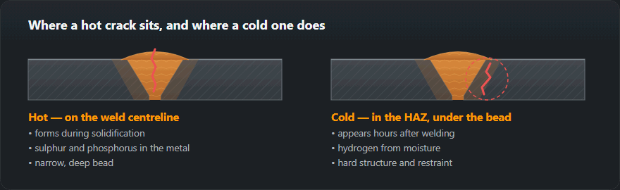
Hot cracking — during solidification
Where: along the centreline of the weld, or in the crater at the end of a run. Visible immediately, sometimes while still welding.
Why: as the weld freezes, the last liquid to solidify is concentrated in low-melting-point compounds — iron sulphide above all — and it sits in a film between the growing grains. The weld is shrinking at the same time, and the film has no strength to resist it.
What makes it worse: sulphur and phosphorus in the parent metal; a deep narrow bead, where the grains grow inwards from both sides and meet in a plane down the middle; high restraint; and stopping the arc without filling the crater.
Cures: a wider, shallower bead — depth-to-width ratio around 1:1 rather than 2:1; low-sulphur consumables; fill every crater; on austenitic stainless, a filler that leaves a few per cent of ferrite in the deposit, which is exactly why 308L is used on 304 rather than a matching composition.
| Factor | Why it matters | What to do |
|---|---|---|
| Sulphur and phosphorus in the metal | They form low-melting films between the grains | Check the certificate, use filler low in S and P |
| A narrow, deep bead | The grains grow towards each other and the centreline stays weak | Make the bead wider and flatter, change the groove |
| High heat input | A bigger pool and a stronger shrinkage | Lower the current or travel faster, see the heat input calculator |
| Rigid clamping | The shrinkage has nowhere to go and stresses build up | Change the welding sequence, free one side |
| An unfilled crater | The shrinkage cavity starts the crack off | Fill the crater, switch on the current down-slope |
Cold cracking — hours after welding
Where: in the heat-affected zone, usually just under the weld toe, running parallel to the fusion line. Often invisible at the surface.
Why: three factors have to coincide. A hard martensitic structure in the heat-affected zone, from cooling too fast. Dissolved hydrogen, from moisture in the consumable or on the plate. And tensile stress, from restraint and shrinkage. Remove any one of the three and the crack does not form.
Cures, in the order they are usually applied: preheat, which attacks the first two factors at once — see the preheat calculator; low hydrogen consumables, properly baked and kept in a quiver; higher heat input, within whatever the WPS allows; and a welding sequence that lets the joint shrink instead of building restraint into it.
Whether the steel is prone to this at all comes from the composition — run it through the carbon equivalent calculator before deciding preheat is unnecessary.
| Condition | How it is removed |
|---|---|
| Hydrogen | Bake the electrodes, store them dry, clean damp, oil and rust off the edges, use electrodes marked H5 |
| A hardened structure | Preheat and keep the interpass temperature in check — the sum is in the CE calculator |
| Stresses | The welding sequence, post-weld stress relief, dropping the rigid clamping |
Lamellar tearing — in the parent metal
Where: in the plate rather than the weld, stepped and running parallel to the surface, under a joint that loads the plate through its thickness.
Why: rolled plate contains flattened non-metallic inclusions lying in the rolling plane. Loaded across the thickness — the short transverse direction — the plate simply has less ductility there, and the inclusions link up.
Cures: this is a design problem more than a welding one. Redesign the joint so the load is not carried through the plate thickness; specify plate with guaranteed through-thickness properties (the Z quality of EN 10164); butter the surface with a low-strength layer before welding the joint; and reduce restraint.
Repairing a crack
Find both ends first — penetrant or magnetic particle testing, because a crack is always longer than the part you can see. Drill stop-holes past each end if the excavation cannot be done in one go. Gouge or grind the whole crack out, re-test the excavation to confirm it has gone, then re-weld to an approved repair procedure, usually with preheat one step above the original.
Where the crack is and what it means
| Where the crack is | Most likely |
|---|---|
| Along the centreline of the weld | Hot, solidification |
| In the crater, star-shaped | Hot, from shrinkage |
| In the heat-affected zone, under the bead | Cold, hydrogen-induced |
| Across the fusion line | Cold or from lack of fusion |
| It showed up hours later | Cold, no question about it |
Crack numbers on a report: 100 to 106
In ISO 6520-1 cracks form group 100, and the number says how the crack runs and where it lies. That is enough for a first guess at the cause:
- 1011 — longitudinal, in the weld metal. Down the weld axis: the typical picture of a hot crack in a narrow, deep bead.
- 1012 and 1013 — longitudinal, on the fusion line and in the HAZ. Under the toe, parallel to the weld: the typical place for a cold crack.
- 1014 — longitudinal, in the parent metal. Outside the weld; in joints that load the plate through its thickness it points to lamellar tearing.
- 102 — transverse. Across the weld; in high-strength weld metal a common sign of hydrogen.
- 104 — crater crack. A star or a short line in an unfilled crater at the end of a run.
- 105 and 106 — group of disconnected cracks and branching crack. A network or a tree; always a reason to look at the material.
Record the number as precisely as the method allows — the full list is in the ISO 6520-1 imperfection numbers table.
Is the steel prone to cold cracking? A worked example
Susceptibility to cold cracking is judged before welding, from the steel’s composition. The site calculator works out the carbon equivalent CE(IIW) = C + Mn/6 + (Cr+Mo+V)/5 + (Ni+Cu)/15 and rates steel below 0.40 as readily weldable, 0.40–0.60 as needing care and above 0.60 as difficult. It estimates preheat by method B of EN 1011-2 — from the CET equivalent, thickness, hydrogen content and heat input.
Example composition: C 0.18; Mn 1.40; Cr 0.05; Mo 0.02; V 0.01; Ni 0.05; Cu 0.10 %. That gives CE = 0.439 — the middle band — and CET = 0.331. With a heat input of 1.0 kJ/mm and a consumable at 5 ml/100 g hydrogen (baked basic electrodes) the calculator gives a preheat of about 80 °C at 20 mm thickness and 110 °C at 30 mm. The same 30 mm with a 10 ml/100 g consumable needs about 140 °C, and with a rutile electrode (about 15 ml/100 g) about 160 °C. The lesson: going from 5 to 10 ml/100 g hydrogen raises the preheat as much as an extra 10 mm of thickness — dry basic electrodes are not a formality. Check your own steel in the carbon equivalent calculator and the temperature in the preheat calculator.
When to test for cracks
A cold crack can appear hours after welding, sometimes a day or more. Testing straight after the last run therefore proves little: “no indications” an hour after welding is not acceptance. For critical joints in steels with a high carbon equivalent, final NDT is scheduled no earlier than 24–48 hours after welding; the actual hold time comes from the product standard or the inspection plan. Surface methods — penetrant and magnetic particle — find cracks open to the surface; cracks under the toe in the HAZ are more reliably found by ultrasonic testing than by radiography, because they are planar.
Mistakes that end in a crack
- Spot preheating. A torch aimed at one place heats only the surface right at the groove. Check the temperature with a temperature crayon or a thermometer on both sides of the joint, not by feel.
- Breaking the arc without filling the crater. The quickest route to a 104 crack — fill the crater or run off onto a run-off tab.
- A narrow, deep bead at any cost. High current at low travel speed in a narrow groove gives a bead deeper than it is wide, and a hot crack down the middle.
- Grinding a crack “clean” without checking. A crack is always longer than it looks; after excavation, test with penetrant or magnetic particles before laying a new run.
- Leaving basic electrodes out of the oven. The example above shows what the extra hydrogen costs in preheat — or, if the preheat is not raised, in cracks.
Why a crack is not permitted at any level, and how that looks in the table of requirements, is on the ISO 5817 quality levels page.
Frequently asked questions
The weld was fine yesterday and cracked overnight. How?
That is the signature of hydrogen-induced cold cracking. It needs time: hydrogen has to diffuse to the point of highest stress before the crack initiates, which typically takes hours and can take up to 48. It is the reason critical joints are inspected a day or two after welding, not straight away.
Can a crack be welded over?
No. It has to be gouged or ground out completely, past both ends, and the excavation checked with penetrant or magnetic particle before re-welding. A crack welded over is still there, now hidden, and it will keep growing.
Does preheating always stop cracking?
It stops cold cracking, which is what it is for: it slows the cooling and lets hydrogen escape. It does nothing for hot cracking — that one is caused by the composition and the bead shape, and preheating can even make it slightly worse by widening the pool.
Is a small crack acceptable at level D?
No. Cracks (group 100 in ISO 6520-1) are not permitted at any of the three ISO 5817 levels — B, C or D — whatever their length. A crack found at inspection is removed completely and the joint rewelded.
How do I tell a hot crack from a cold crack?
By where and when. A hot crack runs down the weld centreline or sits in the crater and is visible straight away; its fracture face is often dark and oxidised. A cold crack lies in the heat-affected zone, usually under the toe and parallel to the fusion line, and may appear many hours later; its fracture face is bright and unoxidised.
Updated: