Reading an ISO 2553 weld symbol: arrow, reference line, dimensions
A welding symbol is a compressed instruction: which joint, which side, what shape, what size, how long, by what process. Read it in that order and it stops being cryptic.
Short answer
You read it in order: the arrow points at the joint, and the side is set by the reference line, not by above or below: in ISO 2553 (system A) a symbol on the solid line belongs to the arrow side, one on the dashed line to the other side. The number before the symbol is the size (a or z), after it the number × length of segments, with the gap between them in brackets. The tail carries the process and the quality level.

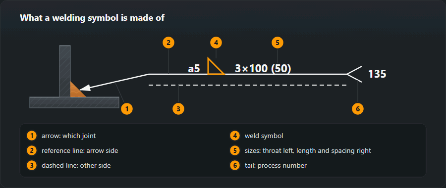
The reading order
1. The arrow. Which joint is being specified. On an asymmetric preparation the arrow is bent and points at the member to be prepared.
2. The line and the side. ISO 2553 system A uses a continuous reference line with a dashed line alongside: symbol on the continuous line means arrow side, on the dashed line means other side. AWS A2.4 uses one line: below it means arrow side, above it means other side.
3. The shape. Triangle — fillet. V — single-V butt. Square — square butt. Half-V — single bevel. U and J — those preparations. A symbol on both sides of the line means welds on both sides.
4. The size, on the left. a followed by a number
is the design throat; z is the leg length. For butt welds the
preparation depth may appear here instead.
5. The length, on the right. A plain number is the length. An
expression such as 3×50 (100) is an intermittent weld: three
segments of 50 mm with 100 mm spaces between them, measured from the
end of one segment to the start of the next (worked through below).
6. The tail. Process number, WPS reference, quality level, NDT requirement — whatever the drawing office chose to put there.

| Symbol | Weld type | When it is used |
|---|---|---|
| Right triangle | Fillet | T-joint, lap, corner |
| Two parallel lines | Square butt (I) | Thin material up to 4–6 mm |
| V | Single-V butt | Roughly 5 to 20 mm thick |
| Half a V | Single-bevel butt | When there is access from one side only |
| U | Single-U butt | Thick material, less filler metal |
| Semicircle | Back weld | A run over the root from the far side |
| Circle | Spot | Resistance welding |
Supplementary symbols
| Mark | Where | Meaning |
|---|---|---|
| Circle | At the elbow | Weld all round the closed contour |
| Flag | At the elbow | Field weld — made on site, not in the shop |
| Straight line over the symbol | On the symbol | Surface to be finished flush |
| Convex arc | On the symbol | Convex surface required |
| Concave arc | On the symbol | Concave surface required |
| M or MR | On the symbol | Permanent or removable backing |
A worked example
A symbol showing a triangle on the continuous line, a5 on its
left, 3×80 (200) on its right, a circle at the elbow and
135 in the tail reads as: a fillet weld on the arrow side, design
throat 5 mm, intermittent — three segments of 80 mm with 200 mm
spaces — running all round the contour, made by MAG welding with solid wire.
Assemble your own and see it drawn in the
welding symbol builder,
and check the a-to-z arithmetic with the
fillet weld
calculator.
The same drawing element means different sides in ISO and AWS. A dashed reference line means ISO; a symbol placed above or below a single line means AWS. Older drawings from the former Soviet system are different again — see GOST 2.312 and ISO 2553.
Weld symbols from a real drawing, taken apart element by element
Below are three symbols that turn up again and again on steelwork shop drawings. Each one is read in the same order: arrow → line → symbol → size on the left → length on the right → marks at the elbow → tail. Stick to that order and nothing gets skipped.
Example 1: a double fillet weld on a T-joint
Two triangles on the reference line, one above the other, each with
a4, nothing on the right, 135 in the tail. There is
no dashed line — and that is correct: ISO 2553 lets you leave it out when a
double-sided weld is symmetrical, meaning the same symbol and the same
dimensions on both sides.
- What: two fillet welds, one on each side of the web.
- How big: design throat
a4, i.e. 4 mm; the leg works out at 4 × 1.41 ≈ 5.7 mm, and that is what the welder checks with a gauge. - How long: no number on the right means a continuous weld along the whole joint.
- How: 135 in ISO 4063 is MAG welding with solid wire.
A sum worth doing before you start: one a4 fillet has a cross-section of a² = 16 mm², two of them 32 mm². Per metre of joint that is 32 cm³, roughly 250 g of weld metal before any reinforcement. Wire consumption is planned from figures like these.
Example 2: a single-V butt weld with a back run
A V on the continuous line, the semicircle of a back run on the dashed line,
111/ISO 5817-C in the tail. Read it as: single-V preparation and
butt weld on the arrow side, with a run over the root from the other side. In the
tail, 111 is manual metal arc welding with covered
electrodes, ISO 5817-C is quality level C, the level the weld will be
assessed against. There is no dimension in front of the V, so full penetration
is required; had the designer accepted partial penetration, a depth such as
s6 would be written there.
In the shop the semicircle on the other side means a specific operation: turn the part over or get underneath it, back-gouge the root to sound metal and lay a run. Plan it into the assembly sequence before the part is welded into a position where its underside can no longer be reached.
Example 3: a column to its base plate, site weld all round
A triangle with a6 on the continuous line, a circle and a flag
at the elbow, 136 in the tail. Read it as: a6 fillet weld on the
arrow side, all round the closed contour, made on site rather than in the shop,
with flux-cored wire under shielding gas (136 in ISO 4063). For a column
made from 200×200 square hollow section that is just under 0.8 m of weld.
Without the circle the weld would cover only the face the arrow touches;
without the flag the shop might weld the plate on before dispatch, and the
column would either not fit on the truck or could not be adjusted on its
anchor bolts.
The a, z and s dimensions and how to convert them
ISO 2553 defines a as the height of the largest isosceles triangle that can be inscribed in the fillet weld section, and z as the leg length. For an equal-leg fillet with a flat face z = a·√2 ≈ 1.41·a, and the other way round a ≈ 0.7·z. The cross-section of such a weld is exactly a², so even a small change in size makes a big difference to the amount of metal:
| a, mm | z = a·√2, mm | Section a², mm² | Weld metal per 1 m, g |
|---|---|---|---|
| a3 | 4.2 | 9 | 71 |
| a4 | 5.7 | 16 | 126 |
| a5 | 7.1 | 25 | 196 |
| a6 | 8.5 | 36 | 283 |
| a7 | 9.9 | 49 | 385 |
| a8 | 11.3 | 64 | 502 |
| a10 | 14.1 | 100 | 785 |
The table is a theoretical minimum: steel at 7.85 g/cm³, no reinforcement, no losses. Going from a4 to a5 adds 56 % more weld metal, from a5 to a7 almost doubles it. Oversizing a weld "to be safe" is not free: it costs wire, hours and distortion. Check the size for a given plate in the throat and leg calculator.
- Unequal legs. The standard says the symbol
amust not be used in that case; the size is specified differently, usually by giving both legs. An a-dimension on an unequal-leg fillet is a reason to ask. - Butt welds. The symbol may be preceded by
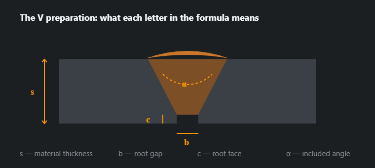
s— the weld thickness including penetration. No dimension next to a butt weld symbol is read as full penetration. - Nominal length in the standard is the length over which
the weld has its full size. End craters do not count, so
a5 200means 200 mm of full a5.
Intermittent welds: n × l (e), worked step by step
The expression on the right of the symbol has three parts: n —
the number of weld elements, l — the length of each,
(e) — the spacing between them. In ISO 2553 the spacing is
measured from the end of one element to the start of the next; PTC's
documentation for the Creo CAD system describes it the same way when it
compares ISO with ANSI/AWS, where the pitch runs centre to centre.

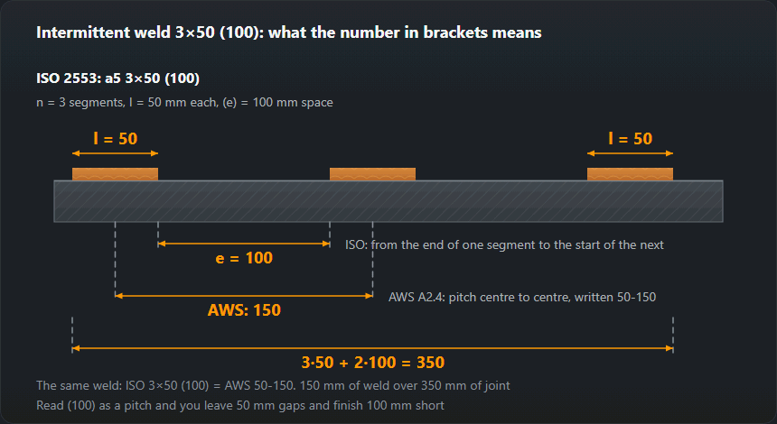
- Length of joint occupied: L = n·l + (n − 1)·e.
For
3×50 (100): 150 + 200 = 350 mm. - Actual weld length: n·l = 150 mm; the rest is spaces.
- How many elements fit: n = (L + e) / (l + e), rounded down. On a 1000 mm joint at 50 (100): 1100 / 150 = 7.3, so 7 elements over 950 mm. That leaves 50 mm — whether the weld must start and finish at the ends of the joint is for the drawing to say, not the welder.
- Converting to AWS: pitch = l + e, so the same weld is
50-150.
A double-sided intermittent weld is either chain — the elements lie opposite one another — or staggered, with the elements on one side opposite the spaces on the other. For a staggered weld the standard also defines the offset: the distance between the start of welding on one side and the start on the other. They are different welds even when the numbers are identical, so look at how the symbols are drawn.
The tail: reading an entry split by slashes
Tail entries are separated by slashes, and each one refers to a different
standard. 135/ISO 5817-C/ISO 6947-PB breaks down like this:
- 135 — the process to ISO 4063 (MAG, solid wire). The commonest numbers are 111, 135, 136 and 141; the full list is in the process number table.
- ISO 5817-C — the quality level imperfections are judged against; what levels B, C and D mean is covered on the ISO 5817 page.
- ISO 6947-PB — the welding position, here horizontal-vertical fillet; the position codes are explained under welding positions.
The tail can also hold a WPS number or inspection requirements. When every weld on the sheet shares the same data, designers often move it into the general notes above the title block — the tails disappear from the symbols and the note applies instead.
Common mistakes when reading weld symbols
- "Above the line means arrow side." A rule picked up from drawings where the dashed line sits below the continuous one. In system A what counts is which line the symbol is on, and the dashed line can be drawn above or below the continuous line. Find the dashed line first, then read.
- Arrow side confused with the visible side. The arrow side is the side the arrow touches, not the side you happen to see in the view. On a section viewed from the other direction the two swap.
- a read as z. A z5 fillet made as a5 gets a 7.1 mm leg instead of 5 mm and twice the cross-section (25 instead of 12.5 mm²). The reverse — a5 made as z5 — gives a throat of about 3.5 mm, 30 % short, and the weld fails inspection.
- The bracket read as a pitch. 3×50 (100) laid with 50 mm gaps finishes 100 mm short and the spaces are too small.
- A missed circle or flag. Without the circle only one face gets welded; without the flag a site weld gets made in the shop.
- A US drawing read as a European one. No dashed line, symbols below a single line and inch dimensions mean AWS. There the fillet size is the leg: 1/4" is a 6.35 mm leg, not a throat.
ISO 2553 system A and system B
ISO 2553 recognises two ways of showing which side of the joint is meant. System A uses a dual reference line — continuous plus dashed — and is based on ISO 2553:1992. System B uses a single line and comes from standards used in Pacific Rim countries, which is why it lines up with AWS A2.4. The standard explicitly forbids mixing the two on one drawing and requires the drawing to state which system it uses, together with the units of measurement.
| System A | System B | |
|---|---|---|
| Reference line | Two: continuous and dashed | One |
| Arrow side | Symbol on the continuous line | Symbol below the line |
| Other side | Symbol on the dashed line | Symbol above the line |
| Compatibility | The European ISO tradition | Deliberately aligned with AWS A2.4 |
How to tell when the title block is silent: if there is a dashed line beside a reference line anywhere on the sheet, it is system A. If there is none and symbols sit above and below a single line, the drawing follows system B or AWS — read it the American way, with the ISO 2553 vs AWS A2.4 comparison to hand.
Frequently asked questions
Where do I start reading?
At the arrow: it tells you which joint. Then the reference line and where the symbol sits on it, which tells you which side. Then the symbol shape, then the dimensions, then the tail. Reading the dimensions before establishing the side is how people weld the wrong face of a plate.
The drawing has no welding symbols at all. Now what?
Ask. An unmarked joint is not "welder's choice" — it is a gap in the documentation, and on anything covered by EN 1090 it has to be resolved before welding. A general note such as "all fillets a4 unless stated" is common and counts as the specification.
What does a symbol on both sides of the line mean?
A weld on both sides of the joint — a double fillet or a double-V butt. The two halves can differ: a5 on one side and a3 on the other is perfectly normal on an asymmetrically loaded joint.
What does 3×50 (100) next to a weld symbol mean?
An intermittent weld: three segments of 50 mm with 100 mm spaces between them. In ISO 2553 the number in brackets is the distance from the end of one segment to the start of the next, not the pitch. The weld therefore occupies 3·50 + 2·100 = 350 mm of the joint and contains 150 mm of actual weld. On an AWS drawing the same weld would read 50-150, because AWS gives the centre-to-centre pitch.
What does a weld symbol with no length on the right mean?
That the weld runs continuously along the full length of the joint. A length is only written when the weld is shorter than the joint or intermittent. An arrow and reference line with no symbol at all means only "weld this joint" — the details then have to come from another document, such as the WPS.
Is BS EN ISO 2553 different from ISO 2553?
Not in content: BS EN ISO 2553 is the UK publication of the same standard, just as DIN EN ISO 2553 is the German one. The current ISO edition is 2553:2019, which replaced the 2013 edition. The standard contains two systems, A and B; European drawings normally use system A with the dashed line.
Updated: