Sheet metal bend allowance calculator
Enter the sheet thickness, inside radius, angle and outside flange dimensions: the calculator gives the flat blank length, the bend allowance (BA) and bend deduction (BD) to DIN 6935, a K-factor from the r/t table or a fixed 0.33/0.44/0.5, and a guide minimum radius for steel, stainless and aluminium.
Short answer
The flat length of an angle is the sum of the outside flange dimensions minus the bend deduction: L = L1 + L2 − BD, where BD = 2·(r + t)·tan(A/2) − BA and BA = π·A/180·(r + K·t) is the arc length along the neutral axis. Example: 2 mm sheet, r = 2 mm, 90° bend, flanges 50 + 50 mm outside. DIN 6935 gives k = 0.65, K = 0.325, BA = 4.16 mm, BD = 3.84 mm and a blank of 96.16 mm. With K = 0.5 it would be 96.71 mm.

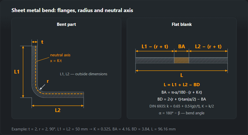
Bend allowance, bend deduction and flat length formulas
In a bend the outer fibres of the sheet stretch, the inner ones compress, and only the neutral axis keeps its length. In thick sheet bent to a small radius it moves towards the inside face, so the arc is taken not at mid-thickness but at x = K·t from the inside face.
- Bend allowance — the arc length along the neutral axis: BA = π·A/180·(r + K·t), where A = 180° − β is the angle the flange is bent through.
- Outside setback from the tangent point to the apex: OSSB = (r + t)·tan(A/2); at 90° it is simply r + t.
- Bend deduction: BD = 2·OSSB − BA. Flat length L = L1 + L2 − BD.
DIN 6935 writes the same thing with the included angle β between the flanges and a correction factor k: L = a + b − v, and for 90° ≤ β ≤ 165° v = 2·(r + t)·tan((180° − β)/2) − π·(180° − β)/180°·(r + t/2·k). The neutral axis lies at x = k·t/2, so the K-factor used in CAD is k/2. For acute bends (β < 90°) the standard dimensions the flanges to the tangents of the outer arc, and the deduction becomes v = 2·(r + t) − BA; above β = 165° it is negligible.
Worked example
50 × 50 angle in 2 mm sheet, r = 2 mm, 90°. r/t = 1, so DIN 6935 gives k = 0.65 + 0.5·log 1 = 0.65, K = 0.325 and a neutral axis x = 0.65 mm from the inside face. The arc BA = 1.5708·(2 + 0.65) = 4.16 mm. The outside setback r + t is 4 mm, which leaves 46.0 mm of straight flange on each side. BD = 2·4 − 4.16 = 3.84 mm and the blank is 100 − 3.84 = 96.16 mm.
Obtuse bend: 3 mm sheet, r = 4.5 mm, β = 120° (bent through 60°), flanges 100 + 100 mm. r/t = 1.5, k = 0.738, K = 0.369. BA = 5.87 mm, BD = 2.79 mm, blank 197.21 mm. Same flanges and radius, but a smaller deduction than a right angle: the gentler the bend, the closer the blank is to the sum of the flanges.
K-factor chart by r/t (DIN 6935)
The DIN 6935 factor k grows with the ratio of inside radius to thickness and reaches 1 at r/t = 5: the neutral axis sits at mid-thickness and K = 0.5. The last column is the flat length of a 50 + 50 mm angle in 2 mm sheet at different radii.
| r/t | k (DIN 6935) | K = k/2 | x at t = 2 mm, mm | r at t = 2 mm, mm | Flat length L, mm |
|---|---|---|---|---|---|
| 0.5 | 0.499 | 0.250 | 0.50 | 1.0 | 96.36 |
| 0.75 | 0.588 | 0.294 | 0.59 | 1.5 | 96.28 |
| 1 | 0.650 | 0.325 | 0.65 | 2.0 | 96.16 |
| 1.5 | 0.738 | 0.369 | 0.74 | 3.0 | 95.87 |
| 2 | 0.801 | 0.400 | 0.80 | 4.0 | 95.54 |
| 3 | 0.889 | 0.444 | 0.89 | 6.0 | 94.82 |
| 4 | 0.951 | 0.476 | 0.95 | 8.0 | 94.06 |
| ≥ 5 | 1.000 | 0.500 | 1.00 | 10.0 | 93.28 |
| 8 | 1.000 | 0.500 | 1.00 | 16.0 | 90.70 |
The familiar CAD values of 0.33, 0.44 and 0.5 correspond under DIN 6935 to r/t of about 1, 3, and 5 or more. How much the choice of K moves the size shows on the same angle:
How much the choice of K matters
| K-factor | K | BA, mm | BD, mm | L, mm |
|---|---|---|---|---|
| DIN 6935 (r/t = 1) | 0.325 | 4.16 | 3.84 | 96.16 |
| K = 0.33 | 0.330 | 4.18 | 3.82 | 96.18 |
| K = 0.44 | 0.440 | 4.52 | 3.48 | 96.52 |
| K = 0.50 | 0.500 | 4.71 | 3.29 | 96.71 |
Between K = 0.325 and 0.5 the difference is 0.55 mm per bend. That is more than the ISO 2768-1 class m general tolerance for 30–120 mm dimensions (±0.3 mm), and on a part with four bends the error adds up. That is why K for a production run is set by a test bend: bend a strip of known length, measure the flanges and adjust K until the calculator returns the same length.
Minimum inside bend radius
The calculator only gives a guide: about 1·t for S235 structural steel, 1–2·t for austenitic stainless, and for aluminium everything depends on the alloy and temper (the soft O temper takes a smaller radius, work-hardened and heat-treated alloys need several thicknesses). The exact values are in the material datasheet, for aluminium sheet in the EN 485-2 tables; for steels made for cold forming (grades with a C, such as S235JRC) the supplier gives the radii.
A tighter radius tears the outer fibres, with the crack running along the bend line. The risk rises when the bend runs parallel to the rolling direction, at plasma-cut or burred sheared edges, and in the cold. In air bending the inside radius is set mainly by the die opening, not by the punch radius — so enter the r your machine actually produces.
What the calculator does not account for
- Springback. The angle opens up when the load comes off and is corrected by overbending; it hardly changes the blank length.
- Bending method. Bottoming and coining shift the neutral axis differently from air bending; the press brake tables from TRUMPF, Amada or Bystronic for a given tool set are more accurate than a general formula.
- Several bends. For a profile with several flanges the deductions add up: L = sum of outside dimensions − sum of BD for each bend.
The press force for the bend comes from the press brake tonnage calculator. The weight of the blank from its size comes from the sheet weight calculator. Shells and reducers are rolled rather than bent — for them there is the cone flat pattern calculator, and for one pipe joining another the pipe saddle template.
Frequently asked questions
How do I calculate the blank length for a bent angle?
Add the outside flange dimensions and subtract the bend deduction: L = L1 + L2 − BD. For 2 mm sheet with r = 2 mm and 50 + 50 mm flanges at 90°, BD = 3.84 mm and the blank is 96.16 mm.
What is the difference between bend allowance and bend deduction?
The bend allowance BA is the arc length along the neutral axis, added to the straight flange lengths. The bend deduction BD = 2·(r + t)·tan(A/2) − BA is subtracted from the sum of the outside dimensions. The result is the same — they are two ways of writing one formula.
What K-factor should I use for steel?
Without press brake data, use DIN 6935 from r/t: k = 0.65 + 0.5·log(r/t) for r/t < 5, otherwise 1; K = k/2. At r = t that is K ≈ 0.325, at r = 3·t 0.444, and at r ≥ 5·t 0.5. For a production run, refine K with a test bend.
How does the DIN 6935 k relate to the K-factor in SolidWorks or Inventor?
It is the same quantity on a different scale. DIN 6935 k gives the neutral axis position from the inside face as a fraction of half the thickness (0…1), the CAD K-factor as a fraction of the full thickness (0…0.5). K = k/2.
What is the minimum bend radius for steel, stainless and aluminium?
As a guide: S235 steel about 1·t, stainless steel 1–2·t, aluminium depending on alloy and temper (EN 485-2 and the datasheet). Bending across the rolling direction tolerates a smaller radius than bending along it.
Updated: