Tacking and welding square tube without distortion
Hollow section is thin metal in a shape that traps heat and concentrates stress at the corners. Two problems, and both are solved before the arc is struck rather than during welding.
Short answer
The current follows the wall, not the outside size of the section. With wire, a wall of 2.0 mm — 90–110, 3.0 mm — 120–140 A; with a stick electrode, a wall of 2.0 mm — 70–90, 3.0 mm — 90–120 A. Tack the corners crosswise or the frame pulls out of square.
Cutting and fit-up
Square tube is unforgiving about cuts. A mitre a degree out leaves a gap on one side and a hard contact on the other, and the weld then pulls the frame towards the tight side as it cools. Cut on a stop, check with a square, and file the burr off both the outside and the inside of the cut.
For a corner joint you have a choice: mitre at 45° for appearance, or butt one tube into the side of the other for strength and simplicity. The butted joint is stronger in most light frames and is far easier to cut accurately.
Tacking is the whole job
Tack two opposite corners, check for square across both diagonals, then tack the remaining two. Measure the diagonals rather than trusting a square — on a frame of any size the diagonals tell you the truth and a square does not.
Any adjustment happens now, while there are only tacks to break. Once the frame is welded, correcting it means cutting.
The welding sequence

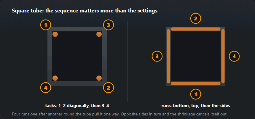
Weld one face, then the opposite face, then the two remaining, again opposite each other. Each weld shrinks as it cools and pulls in its own direction; welding opposite pairs makes those pulls cancel. Running around the perimeter face by face lets them add up, and the frame finishes as a parallelogram.
On thin wall, stitch rather than run — the same logic as thin sheet. Let each stitch lose its colour before starting the next.
The corner itself
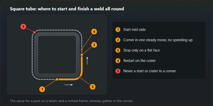
The corner is where the stress concentrates, so it is the worst place for a weld start or an end crater — both are where defects and cracks begin. The ESDEP lecture notes on hollow-section joints (based on CIDECT work) say welding should start in the middle of a side, because starting at the corners lowers fatigue strength.
So start on the flat face and carry the run round the corner in one steady movement — without speeding up, which is the usual reason the corner comes out thin — and finish on the next flat face. If you have to reposition your hands, stop on the flat, not on the corner, and restart over the crater so the new run fuses into the old one.
| Joint | How to weld it | Note |
|---|---|---|
| Mitred frame (45°) | A weld along the outside corner, where the load comes from two sides | Looks good, but the cuts have to be accurate |
| Butted at 90° | A fillet weld on three sides | Easier to fit up, stronger when things are out of square |
| T-joint (post to beam) | A weld right round the contact line | The basic frame joint |
| Open end | Cap it or weld it shut | Otherwise water gets inside and splits the tube at the first frost |

Settings
A closed section holds heat: the second and third faces will need slightly less current than the first, because the frame is already warm. If the last face burns through on settings that worked on the first, that is why.
| Wall, mm | Section | MIG/MAG | MMA |
|---|---|---|---|
| 1.2 | 20×20, 20×40 | 0.8 mm · 50–70 A · 16–17 V | 2.0 mm · 50–65 A, stitch welding |
| 1.5 | 40×20, 40×40 | 0.8 mm · 70–90 A · 17–18 V | 2.0 mm · 55–70 A, stitch welding |
| 2.0 | 40×40, 60×40 | 0.8 mm · 90–110 A · 17–19 V | 2.5 mm · 70–90 A |
| 3.0 | 60×40, 80×40 | 0.8–1.0 mm · 120–140 A · 19–21 V | 3.2 mm · 90–120 A |
| 4.0 | 80×40, 100×50 | 1.0 mm · 140–170 A · 19–21 V | 3.2 mm · 110–140 A |
Typical mistakes
| What went wrong | Cause | How to avoid it |
|---|---|---|
| The frame twisted | Welds run one after another on the same side | Alternate corners, weld in short runs |
| The diagonals came out unequal | Nobody checked them before tacking | Measure both diagonals twice |
| Burnt through the wall | Too much current for 1.2–1.5 mm | Turn it down, stitch it with pauses |
| The corner welded on one side only | Saving time | Weld both sides wherever the joint takes load from two directions |
| Rust from the inside within a year | Open ends | Caps, or weld them shut |
Worked example: a 3000×1500 mm gate leaf
A frame in 60×40×3 box section with mitred corners and one 40×40×2 mid-rail butted into the stiles. The figures come from the same tables that drive the hollow section calculator and the settings table above:
- Steel. The frame is 9.0 m of tube at 4.25 kg/m, so 38.3 kg; the rail is 2.92 m at 2.31 kg/m — 6.7 kg. About 45 kg in total before infill, hinges and lock: two people can lift it, but the hinges and the post have to carry it with the full width as a lever arm.
- Weld length. Each mitred corner is the perimeter of a 60×40 section, 800 mm for four corners, plus 320 mm for the two rail ends. That is 1.12 m of weld in all — very little, so the time goes on cutting, fitting and checking diagonals, not on the arc.
- Settings. Frame corners (3 mm wall): wire 0.8–1.0 mm, 120–140 A, 19–21 V, or a 3.2 mm electrode at 90–120 A. The rail (2 mm wall) needs you to drop to 90–110 A and 17–19 V, or a 2.5 mm electrode at 70–90 A. Leave the frame settings on and you blow through the rail wall in the first centimetre.
The order for this leaf: tack the four corners diagonally, check the diagonals, tack the rail on both sides, check the diagonals again. Then weld the corners in diagonal pairs and the rail last — its welds are the shortest and pull the least.
The same box section carries ready-made projects with a cutting list and parts list — a fence, a door canopy and steel stairs; all of these calculators are gathered on the project calculators page.
Thin tube to a thicker part
The most common joint in practice is not tube to identical tube but 2 mm tube to a 3 mm post, to a hinge flat or to a base plate. The rule is simple: set the machine for the thinner wall and aim the arc at the thicker part. The thick part takes the heat without burning through and sinks it away, while the pool wets onto the thin wall by itself.
- Set the current from the table for the thinner wall.
- Angle the gun so the wire points into the thick part, right at the edge of the tube.
- On a post base plate, start in the middle of a face, not on the corner of the tube — the corner heats up fastest.
- Weld opposite faces in turn, exactly as on a frame: front, back, left, right.
A gate post base plate is a load-bearing joint: the weld goes all the way round, and the fillet size is calculated, not guessed — fillet weld size calculator.
Posts on site: vertical welds and wind
A post set in concrete or bolted to a footing is welded where it stands — that means vertical, and often in the wind. Thin non-structural parts such as pickets and infill can be welded vertical-down in short-circuit transfer, fast and with little heat; technique — vertical-down welding. A structural post and its base are welded vertical-up: downhill gives shallow penetration and lack of fusion that you cannot see from the outside.
Wind blows the MIG gas shield away and leaves porosity. Outdoors a stick electrode or self-shielded 114 wire works better — flux-cored wire. The minimum for MIG is a screen of sheet or tarpaulin on the windward side.
Galvanised and painted tube
Zinc boils off in the arc as white fume, and metal fume fever follows. Grind the weld area back to bare steel on both sides and weld with extraction or a filtered mask — welding fume. On zinc the weld also picks up porosity, because the zinc vapour bubbles through the pool.
If the finished frame is going for hot-dip galvanising, sealing the tubes is a mistake: a closed volume dipped in molten zinc can burst. EN ISO 14713-2 calls for vent and drain holes in every enclosed section — agree their position with the galvaniser before you weld. A frame for powder coating needs the opposite: continuous welds with no crevices where pre-treatment chemicals can collect.
Checks after welding
- Diagonals — the final measurement once the frame has cooled on the table; more than 2 mm per metre of difference means the frame is out of square.
- Flatness — laid on a flat table, the frame must not rock across a diagonal; a twisted gate leaf will never close flush against the post.
- Corners — a crater at the end of a weld right on the corner is the typical crack starter; fill it by holding the gun still for a moment before breaking the arc.
- Undercut on thin wall — on 1.5 mm a groove along the toe eats a real share of the thickness; how to spot it — undercut.
Frequently asked questions
What settings for 2 mm wall?
MIG short arc, 0.8 mm wire, about 90–110 A at 17–19 V. Test on an offcut of the same section: 2 mm wall behaves differently from 2 mm flat sheet, because the closed section has nowhere to lose the heat.
Do I need to weld all the way round?
Only if the drawing says so. A fully sealed section cannot admit moisture, which matters outdoors; but a continuous weld all round puts far more heat in and pulls the frame more. On light frames a stitched weld with sealed ends is often the better engineering answer.
The frame keeps coming out of square.
Sequence, not skill. Tack diagonally, weld opposite faces in turn, and use a jig or a stop block. A frame that is welded face by face round the perimeter will always pull towards the last weld.
What stick electrode for 2 mm wall square tube?
A 2.5 mm rutile electrode at 70–90 A. On 1.5 mm wall drop to a 2.0 mm electrode at 55–70 A and weld in short stitches.
MIG or stick for square tube?
On 1.2–2 mm wall MIG is easier: less heat, no slag and a thin edge is easier to hit. Stick wins in the wind, on site and on walls of 3 mm and up, where burn-through stops being the main problem.
How do I weld square tube to a base plate?
Set the machine for the tube wall and aim the arc at the plate. Start in the middle of a face, not on the corner, and weld the faces in turn: front, back, left, right. Weld all the way round, because it is a load-bearing joint.
Can a frame going for hot-dip galvanising be fully sealed?
No. A sealed tube in the zinc bath can burst, so EN ISO 14713-2 requires vent and drain holes in every enclosed section. Agree their position with the galvaniser before welding.
Updated: