Weld joint preparation
The preparation decides how much filler goes into the joint, whether the root is penetrated and whether the weld binds to the side wall. Below are the angle, root face and gap for every thickness to ISO 9692-1 — and what sits behind those numbers.

Short answer
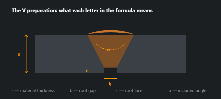
Every edge preparation is described by four dimensions:
- s — thickness of the material being joined;
- α — included angle, the opening of the groove;
- c — root face, the unbevelled part of the edge at the root;
- b — root gap between the parts.
The choice comes down to two questions: what thickness and is there access from both sides. Up to 3–4 mm nothing is bevelled at all, up to 12 mm a single-V is enough, above that a double-V with two-sided access or a U with one-sided.
Thickness and preparation
| Thickness s, mm | Preparation | Angle α | Root face c, mm | Root gap b, mm | When |
|---|---|---|---|---|---|
| ≤ 3 … 4 | I — square edge | — | — | 0–3 | Thin material: the gap alone gives penetration |
| 3 … 12 | Single-V | 50–70° | 1–2 | 1–4 | The default when access is from one side only |
| 12 … 40 | Double-V (X) | 50–60° | 1–3 | 1–3 | Access from both sides: about half the deposit of a single-V |
| > 30 | Single-U | 8–12° | 1–3 | 1–3 | Heavy plate, one-sided access; needs machining |
| > 40 | Double-U | 8–12° | 1–3 | 1–3 | Very heavy plate, access from both sides |
| 5 … 20 | Single-bevel (½V) | 45–55° | 1–3 | 1–3 | T-joint with full penetration |
| > 15 | Double-bevel (K) | 45–55° | 1–3 | 1–3 | T-joint with full penetration, access from both sides |
| — | Fillet, no preparation | — | — | 0–2 | Where full penetration is not required |
The angle follows the process
The same plate gets a different angle for MMA and for MAG, and that is not a matter of habit:
| Process | Included angle α | Why |
|---|---|---|
| MMA (111) | 60° | A covered electrode needs room to enter the groove and for the slag to be chipped off |
| MAG (135) | 50–60° | The arc digs deeper, so the groove can be narrower — less deposit and less shrinkage |
| TIG (141) | 60–70° | The torch is wide and the pool has to stay visible; a narrow groove invites lack of fusion |
The difference looks small, but on 20 mm plate going from 60 to 50 degrees cuts the groove area by about a fifth — the same fifth off the filler, the gas and the time for every metre of weld.
ISO 9692-1 covers arc welding of steels — that is where the numbers above come from. -2 deals with submerged arc welding of steels, -3 with MIG and TIG welding of aluminium, -4 with clad products. Aluminium takes different angles from steel, so carrying these tables over to it is a mistake.
Why this is not a free choice
Too narrow a groove means lack of side-wall fusion (4011). The electrode cannot reach the root at the right angle, the arc grazes the flank, and the weld metal lies against it without joining. A planar defect, not permitted at any quality level of ISO 5817 — and the hardest of all to catch on a radiograph.
Too wide a groove is not safer, only dearer. The area grows with the opening, so every extra ten degrees costs roughly a fifth more filler, gas and time. With the filler goes the heat input, and with the heat input the shrinkage and distortion: the more metal you put in, the further the structure moves as it cools.
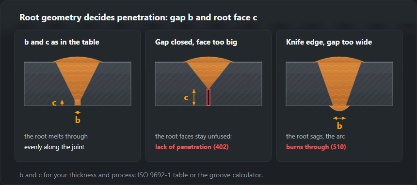
Too large a root gap ends in burn-through (510) or a sagging root, too small a one in incomplete penetration (402): the arc has nothing to reach the root with. That is why the gap is set at tacking and held to a gauge, not judged by eye after grinding.
The root face is what saves the root from burning away. Without it the first run burns through the joint; with it the root melts under control. Too large a root face brings the opposite trouble: the root is never penetrated.

How the edge is prepared
The order never changes: cut — remove the dross and the overheated layer — clean — tack while holding the gap.
After flame and plasma cutting the edge carries a layer of oxides and a heat-affected zone; it is ground back to bright metal, otherwise the oxides end up in the pool and come out as inclusions (303). Plasma adds dross on the underside of the cut — that gets removed, not welded over.
Cleanliness applies not only to the groove itself but to 20–30 mm either side of it. Rust, paint, zinc, oil and moisture are sources of hydrogen and porosity: paint and oil give pores straight away, zinc adds highly toxic fume, and condensation on cold or wet plate remains the commonest cause of porosity in an unheated workshop.
U and double-U preparations are machined — milled or run on an edge bevelling machine. A torch cannot produce that profile, and trying to "approximate" it with a wide V eats the very saving the U was chosen for.
Weld joint preparation step by step
The table says what the groove should look like; the sequence below is how it gets that way in a workshop. Each step that gets skipped turns up later as a defect of its own, and the note after each step says which one.
- Read the drawing and the WPS. The weld symbol gives the groove shape, and often the angle, root face and gap; the WPS gives the process and the ranges that were qualified. If the two disagree, the welder works to the WPS and the question goes back to the engineer. How the symbol reads — welding symbols.
- Choose how the bevel will be cut — by material, thickness and how accurate the root face has to be (the next section compares the methods).
- Mark and cut. Scribe the root-face line along the edge before cutting: a line is far easier to follow with a torch or a grinder than an estimate.
- Dress the cut face. Grind off oxide, dross and the overheated layer down to bright metal. Check the angle with a bevel gauge and the root face with a caliper at both ends and in the middle. An uneven root face gives a root that alternates between burn-through and lack of penetration.
- Clean the surroundings — 20–30 mm either side of the groove, and on the back face too where the root will come through. Degrease first, brush or grind second: a wire brush run over oil only spreads it.
- Fit up. Set the gap with spacers (a length of wire or a feeler of the right size), tack the ends first and then the middle, and re-check the gap after every tack — each tack shrinks and pulls the gap closed. Check the edges line up: a step between them leaves the low side unfused, as described under lack of penetration.
- Check before the root run. Gap along the whole length, root face, cleanliness, tacks ground to a taper so the root bead can run over them, and preheat if the steel calls for it — the preheat calculator tells you whether it does.
Cutting and bevelling methods: what each leaves on the edge
Every method produces the angle; they differ in what they leave on the face and in how much work remains before the first run.
| Method | Suitable for | What it leaves on the edge | Before welding |
|---|---|---|---|
| Oxy-fuel cutting | Unalloyed and low-alloy steel, medium and heavy plate. Does not cut stainless steel or aluminium | Oxide scale, slag on the underside, a hardened edge on higher-carbon steels | Grind to bright metal; on hardenable steels look for cracks along the edge |
| Plasma | Any conductive metal, stainless and aluminium included | Dross on the underside, an oxidised or discoloured face, a slight taper across the cut | Remove the dross, grind the face |
| Laser | Thin and medium sheet, accurate parts | A narrow heat-affected zone; a thin oxide film when oxygen is the cutting gas | Remove the oxide film, degrease |
| Bevelling machine, edge milling | Long straight edges, pipe ends, U grooves, stainless steel | A clean, cold-cut face with an accurate angle and root face | Degrease only |
| Angle grinder | Short joints, repairs, site work | Angle and root face as good as the hand that held it | Check the angle with a gauge and watch the root face |
| Carbon arc gouging | Back-gouging the root, digging out defects | A carbon-enriched surface layer and slag | Grind the surface layer off before welding |
Why a flame-cut edge can be hard: the strip along the cut is heated above the transformation temperature and then quenched by the cold plate behind it. On mild steel this does not matter; on steels with a higher carbon equivalent the edge can harden enough to crack under the shrinkage of the first run. That is the reason for grinding the face back, not only for looks.
Preparing stainless steel and aluminium
Stainless steel needs its own tools: discs, files and stainless-wire brushes that have never touched carbon steel. Particles of ordinary steel pressed into the surface rust later and leave brown spots along the weld. The oxidised face from plasma or laser cutting is ground off, and on pipe and on joints where the root side matters the backing gas is planned before fit-up, not after — more in welding stainless steel.
Aluminium is covered by an oxide that melts at about 2050 °C, while the metal melts at 660 °C. The order is: degrease with a solvent, then brush with a stainless brush kept for aluminium only, and weld soon after, because the film grows back. Groove angles for aluminium come from ISO 9692-3, not from the steel table above — see welding aluminium.
Common joint preparation mistakes and how they show up
- Bevel ground by eye, root face wandering along the joint — the root alternates between burn-through and lack of root penetration (402).
- Knife edge with no root face and a wide gap — burn-through (510) and a sagging root.
- Gap pulled shut by the tacks — lack of root penetration over exactly the length between two tacks.
- Groove too narrow for the electrode or torch — side-wall lack of fusion (4011), explained under lack of fusion.
- Dross or oxide left on a plasma-cut face — oxide inclusions (303) and porosity.
- Primer or zinc left beside the groove — pores in the weld and toxic fume at the arc, see welding fume.
- A gouged root left as gouged — porosity and inclusions in the back run.
- Preparation taken from the table rather than from the access — a V on a part that could have been turned, or an X on one that cannot be.
Worked example: 20 mm plate, MAG
With access from both sides the table gives an X preparation: 50–60°, gap 1–3 mm, root face 1–3 mm. The calculator puts its cross-section at about 137 mm², or 1.07 kg of weld metal per metre. If the part cannot be turned, the same plate takes a V: about 240 mm² and 1.88 kg per metre. Turning the part saves more than two fifths of the weld metal.
The order of work for the X: cut and dress both bevels, tack with a gap of about 2 mm, weld the root from the first side, turn the part, back-gouge or grind the second side to sound metal, then fill the two sides alternately so the angular shrinkage of one balances the other.
What next
The figures for your own thickness, process and access come from the joint preparation calculator — the same numbers as in the table above. How much filler and how many electrodes a joint prepared this way will swallow is worked out by the electrode consumption calculator. How the preparation is recorded on a drawing — welding symbols. What poor preparation turns into — lack of fusion and penetration.
Frequently asked questions
At what thickness do you start bevelling?
Around 3 mm for MMA and TIG, 4 mm for MAG — the MAG arc digs deeper and copes longer without a groove. Below that the root gap alone gives penetration, and a bevel only adds deposit and distortion.
Single-V or double-V on 20 mm plate?
If both sides are accessible, double-V. It takes about 40 % less deposit than a single-V (see the worked example: 137 against 240 mm² on 20 mm plate with MAG) and far less angular shrinkage, because the weld sits symmetrically about the mid-plane. With access from one side only you are left with the single-V, and on heavier plate the U — it removes even less metal, but the flank has to be machined.
What does too narrow a groove cost you?
Lack of side-wall fusion, 4011 to ISO 6520-1: the arc grazes the flank instead of melting it. As a planar defect it is not permitted at any ISO 5817 level, and it is the hardest defect to see on a radiograph — the cause and the fix are in the section on why the groove is not a free choice.
What does weld joint preparation include?
Four things, in this order: the groove shape and its dimensions (angle, root face, gap), dressing the cut face (oxide, dross and the overheated layer ground off), cleaning 20–30 mm either side of the groove, and fit-up — gap, tacks and alignment of the edges. Skip any one and it comes back as its own defect: lack of fusion, lack of penetration, inclusions or porosity.
Can you bevel stainless steel or aluminium with an oxy-fuel torch?
No. Oxy-fuel cutting works on unalloyed and low-alloy steel only; stainless steel and aluminium are cut by plasma or laser or bevelled mechanically. For stainless, use discs and brushes that have never touched carbon steel.
Do you have to grind the edge after plasma cutting?
Yes. Plasma leaves dross on the underside and an oxidised face; left in place, both end up in the pool as inclusions and porosity. Grind the face to bright metal and check the angle and the root face with a gauge while you are at it.
Updated: